
Real-time clock synchronization error correction method for fee-controlled smart energy meters

A smart energy meter and real-time clock technology, applied in the measurement of electrical variables, measuring devices, instruments, etc., can solve the problems that affect the normal use of cost-controlled smart energy meter measurement and settlement, the impact of real-time clock accuracy, and the inconsistency of binary digits. To achieve the effect of enhancing the anti-interference ability of the clock, reducing the frequency of reading the external clock, and reducing the probability of being interfered

Active Publication Date: 2017-07-07
武汉阿迪克电子股份有限公司
View PDF10 Cites 2 Cited by
  • Summary
  • Abstract
  • Description
  • Claims
  • Application Information

AI Technical Summary

Problems solved by technology

[0003] However, when the existing cost-controlled smart energy meters are running, they need to read the time data from the external clock chip in real time
In the frequent communication process, since the communication signal with the external clock chip is transmitted in the physical channel, the random noise caused by the electrical characteristics of the line itself, the attenuation of the signal amplitude, the distortion of the frequency and phase, and the reflection of the electrical signal on the line are caused. Echo effects, crosstalk between adjacent lines, and various other external factors (such as lightning in the atmosphere, flashover of switches, changes in external strong current magnetic fields, fluctuations in power supply, etc.) will cause signal distortion
This will make the binary digits received by the microcontroller inconsistent with the binary digits actually sent by the external clock chip, resulting in errors from "0" to "1" or from "1" to "0".
In this way, the accuracy of the real-time clock will be affected, thus affecting the normal use of functions such as metering and settlement of the fee-controlled smart energy meter

Method used


Image

  • Real-time clock synchronization error correction method for fee-controlled smart energy meters
  • Real-time clock synchronization error correction method for fee-controlled smart energy meters

Examples


Embodiment Construction

[0035] Embodiments of the present invention will be described in further detail below in conjunction with the accompanying drawings.

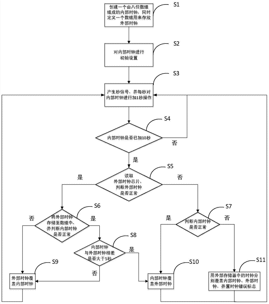
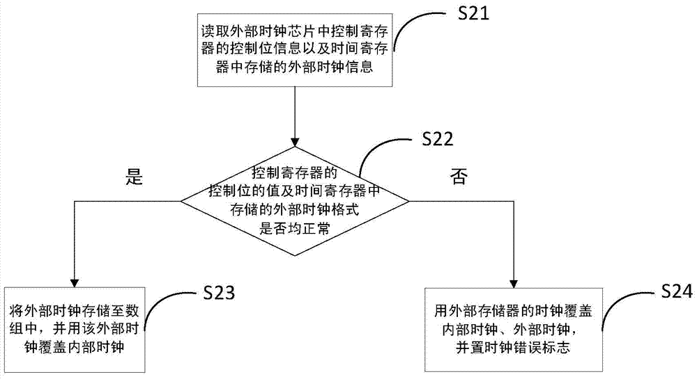
[0036] Such as figure 1 As shown, the present invention provides a real-time clock synchronous error correction method for a fee-controlled smart electric energy meter. The electric energy meter is internally provided with a single-chip microcomputer, an external clock chip capable of generating an external clock, and an external memory storing clock data, and the single-chip microcomputer is respectively Connect with external clock chip and external memory. The real-time clock synchronization error correction method comprises the following steps:

[0037] S1. Create an internal clock consisting of an eight-digit array inside the microcontroller, set it as inside_date[8], and store seconds, minutes, hours, weeks, days, months, years, and checksums in this eight-digit array in turn; define at the same time A seven-digit array is used to store ...


PUM


Abstract

A real-time clock synchronous error correction method for a cost-controlled intelligent electric energy meter, relating to the technical field of electric energy metering instruments, comprising the steps of: first creating an internal clock inside a single-chip microcomputer, and defining an array for storing external clocks; powering on the electric energy meter Initially set the internal clock after startup; then generate a second signal through the timer, and add 1 second to the internal clock every second; every time the internal clock is added for 10 seconds, the external clock and the internal clock are checked in turn , and perform corresponding synchronous error correction processing on the abnormal clock. The invention can enhance the anti-interference ability of the clock, effectively guarantee the accuracy of the real-time clock in the electric energy meter, and is stable and reliable.

Description

technical field [0001] The invention relates to the technical field of electric energy metering instruments, in particular to a real-time clock synchronous error correction method for a fee-controlled intelligent electric energy meter. Background technique [0002] With the use of single-chip microcomputers and smart chips in electric energy meters, multi-functional cost-controlled intelligent electric energy meters have also been more and more widely used. Since some functions in the cost-controlled smart energy meter require the cooperation of the clock, such as time-of-use measurement, automatic electricity settlement, etc., these functions involve the electricity measurement and settlement of the energy meter, so accuracy is particularly important. The clock plays an important role in it, so it is necessary to ensure the accuracy of the clock. [0003] However, when the existing cost-controlled smart energy meters are running, they need to read the time data from the ex...

Claims


Application Information

Patent Timeline
Patent Type & Authority Patents(China)
IPC IPC(8): G01R35/04
Inventor 徐健刘艳红李良红刘金刚陶永法连小华汪伟
Owner 武汉阿迪克电子股份有限公司
Learn More