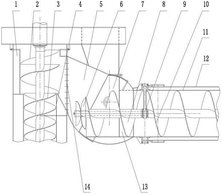
Coaxial ring-shaped material groove material transferring device
A ring-shaped, trough technology, applied in the field of coaxial ring-shaped trough material transfer device, can solve the problem of increasing the energy consumption of vertical screw conveyors and horizontal screw conveyors, reducing the service life of support structures, and easily bonding and agglomerating materials and other problems to achieve the effect of avoiding material bonding and agglomeration, avoiding partial load, and improving uneven force
- Summary
- Abstract
- Description
- Claims
- Application Information
AI Technical Summary
Problems solved by technology
Method used
Image
Examples
Embodiment 1
[0026] Such as figure 1 As shown, the coaxial annular trough transfer device includes a vertical screw conveyor with a discharge port 14 and a vertical support pipe 1, a horizontal screw conveyor with a horizontal support pipe 12, an annular discharge chute 5 and an annular inlet. The chute 7, the annular discharge chute 5 are connected with the discharge port 14 through the flange, the annular feed chute 7 is connected with the horizontal screw conveyor through the flange, and the annular discharge chute 5 is hinged with the annular feed chute 7 , the ring centers of the annular discharge chute 5 and the annular feed chute 7 are the hinge points of the annular discharge chute 5 and the annular feed chute 7; The ring structure with the hinge point as the center of the ring ensures that the material can be transferred smoothly when the horizontal support tube is pitched to different positions.
[0027] The vertical screw conveyor includes a vertical conveying screw 3 and a ver...
Embodiment 2
[0032] The difference between this embodiment and Embodiment 1 is that the upper end of the vertical conveying screw 3 is connected with a discharge screw 2, the discharge screw 2 is composed of an upper spiral blade and a lower spiral blade, and the lower spiral blade is connected with the upper end of the vertical conveying screw 3 , the inner wall of the upper helical blade is close to the outer wall of the lower helical blade, and the turning direction of the vertical conveying screw 3 is the same as that of the lower helical blade, and opposite to that of the upper helical blade; the materials are dispersed under the drive of the upper helical blade and the lower helical blade, so that The material transportation process is smoother.
[0033] The diameters of the upper helical blade and the lower helical blade are larger than the diameter of the vertical conveying screw 3; it is not easy to scatter when feeding materials.
Embodiment 3
[0035] The difference between this embodiment and Embodiment 1 and Embodiment 2 is that the other side of the end suspension bearing 9 is connected with a cantilever feed screw 8, and the cantilever feed screw 8 is located in the annular feed groove 7; the present invention When working, the cantilever feeding screw 8 rotates, so that there is no dead angle of material movement in the junction between the annular discharge trough and the annular feed trough, and the material is prevented from sticking and agglomerating.
PUM
 Abstract
Description
Claims
Application Information
 - R&D
- Intellectual Property
- Life Sciences
- Materials
- Tech Scout
- Unparalleled Data Quality
- Higher Quality Content
- 60% Fewer Hallucinations
Browse by: Latest US Patents, China's latest patents, Technical Efficacy Thesaurus, Application Domain, Technology Topic, Popular Technical Reports.
© 2025 PatSnap. All rights reserved.Legal|Privacy policy|Modern Slavery Act Transparency Statement|Sitemap|About US| Contact US: help@patsnap.com

