
Electrohydraulic Coupled Vehicle Suspension Impedance Control Device

A vehicle suspension and impedance control technology, applied in the automotive field, can solve the problems of invariable impedance of mechanical suspension and complex suspension structure, and achieve the effects of superior dynamic performance, increased adjustable range, and flexible impedance form.

Active Publication Date: 2017-01-18
JIANGSU UNIV
View PDF9 Cites 0 Cited by
  • Summary
  • Abstract
  • Description
  • Claims
  • Application Information

AI Technical Summary

Problems solved by technology

[0004] Aiming at the problem that the mechanical suspension impedance is invariable and the specific suspension structure obtained through network synthesis is relatively complex and easily includes lever elements, the present invention proposes a vehicle suspension impedance control device that can realize complex impedance forms

Method used


Image

  • Electrohydraulic Coupled Vehicle Suspension Impedance Control Device
  • Electrohydraulic Coupled Vehicle Suspension Impedance Control Device
  • Electrohydraulic Coupled Vehicle Suspension Impedance Control Device

Examples


Embodiment Construction

[0019] The present invention will be further described below in conjunction with the accompanying drawings and specific embodiments. It should be pointed out that the technical solution and design principles of the present invention will be described in detail below only with an optimized technical solution, but the protection scope of the present invention does not limited to this.

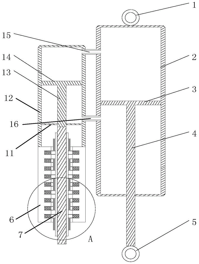
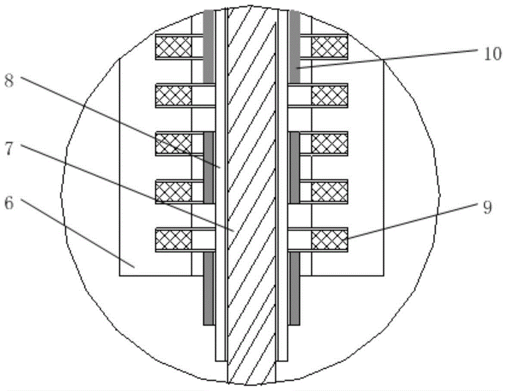
[0020] Such as figure 1 with figure 2 As shown, a hydraulic-electric coupling type vehicle suspension impedance control device includes an upper lifting lug 1, a main hydraulic cylinder 2, a lower lifting lug 5, an auxiliary hydraulic cylinder 11, a mover shaft 7 and a motor stator 6, wherein the upper lifting lug 1 It is welded together with the main hydraulic cylinder 2, and the lower lifting lug 5 is welded together with the main piston rod 4. The upper lifting lug 1 is hinged with the vehicle body, and the lower lifting lug 5 is hinged with the wheel.

[0021] The main hydraulic cylinder 2...


PUM


Abstract

The invention provides a liquid electric coupling type vehicle suspension impedance control device which comprises an upper lifting lug, a main hydraulic cylinder, a lower lifting lug, an auxiliary hydraulic cylinder, a rotor shaft and a motor stator. The upper lifting lug is connected with the upper end of the main hydraulic cylinder. The main hydraulic cylinder and the auxiliary hydraulic cylinder are arranged side by side. Upper cavities and lower cavities of the main hydraulic cylinder and the auxiliary hydraulic cylinder are communicated through connection pipes respectively. The main hydraulic cylinder is internally provided with a main hydraulic cylinder piston and a main piston rod which are connected in a matched mode. The lower end of the main piston rod is fixedly connected with the lower lifting lug. The auxiliary hydraulic cylinder is internally provided with a baffle, an auxiliary piston rod and an auxiliary hydraulic cylinder piston, wherein the middle of the baffle is provided with holes, and the auxiliary piston rod and the auxiliary hydraulic cylinder piston are connected in a matched mode. The lower end of the auxiliary hydraulic cylinder is fixedly provided with the motor stator evenly provided with windings, and the windings are connected with an outer-end control circuit. A rotor shaft provided with a rotor magnetic yoke and rotor magnetic poles penetrates through a motor working cavity and is fixedly connected with the auxiliary piston rod. The impedance control device is more flexible in impedance form, superior in dynamic performance and small in nonlinear factor influence, a split structure of the impedance control device is achieved and space is saved.

Description

technical field [0001] The invention belongs to the field of automobiles, in particular to a hydraulic-electric coupling type vehicle suspension impedance control device. Background technique [0002] In 2002, Smith, a scholar at the University of Cambridge, proposed the concept of an inerter and provided a realization device. Like the spring and damper in a mechanical system, it is a real two-terminal element. The force at both ends is proportional to the corresponding acceleration at both ends, and its proportional constant is called "coefficient of inertia", and the unit is kilogram. With the proposal of the inerter, the "Inerter-Spring-Damper" (ISD for short) vehicle suspension composed of the three basic components of the inerter, spring and damper improves the vibration isolation performance of the suspension. Many scholars have carried out research on the structural design of vehicle ISD suspensions, using algorithms such as robust control for the passive mechanical ...

Claims


Application Information

Patent Timeline
Patent Type & Authority Patents(China)
IPC IPC(8): B60G13/14B60G17/015F16F15/023F16F15/03
Inventor 杨晓峰沈钰杰杨军刘雁玲汪若尘
Owner JIANGSU UNIV
Learn More