
Method of operation and a control program for a central unit in an automation system

a technology of automation system and control program, which is applied in the direction of programme control, multi-programming arrangement, electric controller, etc., can solve the problems of low dynamics, no longer guaranteed deterministic response, and control program that does not provide prior knowledge to the central unit. achieve the effect of high dynamics

Active Publication Date: 2006-11-21
SIEMENS AG
View PDF6 Cites 27 Cited by
  • Summary
  • Abstract
  • Description
  • Claims
  • Application Information

AI Technical Summary

Benefits of technology

[0010]The object of the present invention is to provide a possible means of changing from one subprogram to another subprogram in the course of operation of the central unit, and of still achieving high dynamics for the control program, with a deterministic response from the control program still being ensured at the same time.

Problems solved by technology

In particular, the control program does not provide the central unit with prior knowledge of how many and what subprograms are active at what time.
Since the dynamics of the control program are determined essentially by the cycle time, however, only relatively low dynamics can be provided.
In this case, although the response of the controlled process would be as dynamic as possible, the varying cycle time would mean that a deterministic response would no longer be ensured.

Method used


Image

  • Method of operation and a control program for a central unit in an automation system
  • Method of operation and a control program for a central unit in an automation system
  • Method of operation and a control program for a central unit in an automation system

Examples


Embodiment Construction

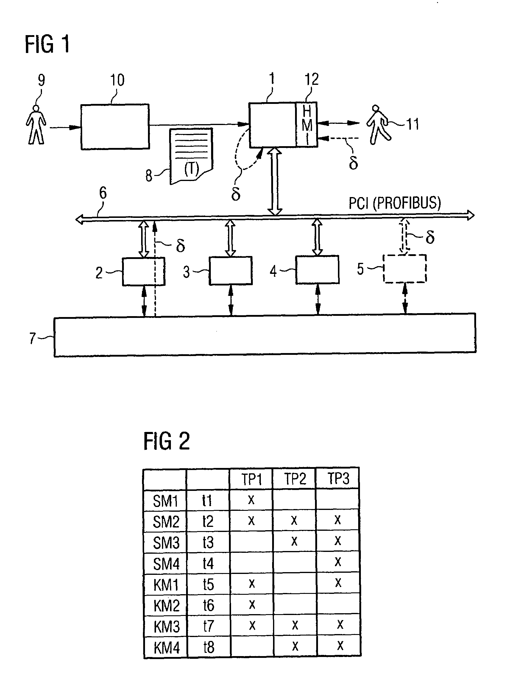
[0026]According to an embodiment illustrated in FIG. 1, an automation system has a central unit 1 and peripheral modules 2 to 5. The central unit 1 is connected to the peripheral modules 2 to 5 by means of a bus 6 and is thus capable of communicating with the peripheral modules 2 to 5.

[0027]The peripheral modules 2 to 5 may be central peripheral modules 2 to 5. In this case, the automation system is in the form of a central automation system. The bus 6 may alternatively be a serial bus 6 or a parallel bus 6 in this case. An example of a serial bus 6 which is used in a central automation system is the bus in the S7-300 controller from Siemens AG. An example of a parallel bus 6 is, as indicated in FIG. 1 by the letters “PCI”, the PCI bus known from computer engineering.

[0028]Alternatively, the peripheral modules 2 to 5 may be local peripheral modules 2 to 5. In this case, the bus 6 is normally in the form of a field bus 6, e.g. in the form of an IRTE (Industrial Real Time Ethernet), i...


PUM


Abstract

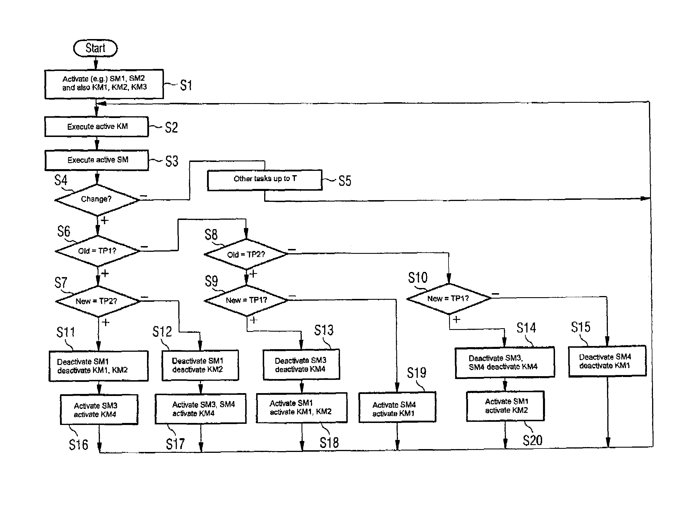
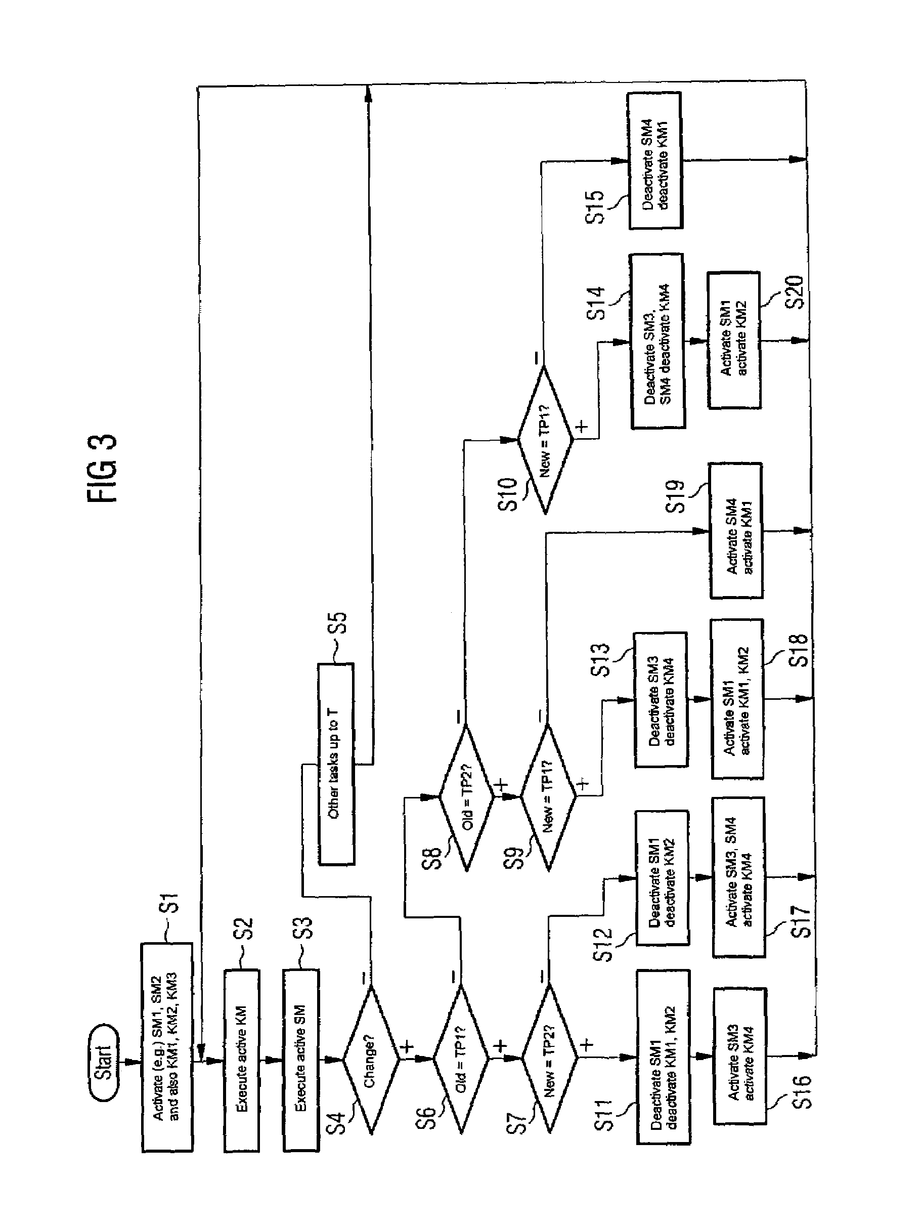
The present invention is directed to a method of operation and a control program for a central unit (e.g., CPU) in an automation system repeatedly executing a control program that is stored in the central unit and comprises at least two subprograms. A single instance of execution occurs within a cycle time which is stipulated by the control program. The central unit executes only one of the subprograms—the activated subprogram—at a time. The cycle time is independent of the activated subprogram, is shorter than the time required in order to execute all of the subprograms, and is at least as long as the longest time period required in order to execute one of the subprograms once.

Description

FIELD OF THE INVENTION[0001]The present invention relates to a method of operation for a central unit (e.g., central processing unit or CPU) in an automation system, where the central unit repeatedly executes a control program which is stored in the central unit. A single instance of execution of the control program occurs within a cycle time which is stipulated by the control program.BACKGROUND OF THE INVENTION[0002]The present invention also relates to a control program for carrying out such a method of operation, in a central unit of an automation system and in an automation system itself.[0003]Automation systems, their central units, and also methods of operation and control programs for central units are general knowledge.[0004]In the prior art, it may be that the control program comprises at least two subprograms, with only one of the subprograms being activated at a time and the central unit executing only the activated subprogram. One example of such a situation involves, by...

Claims


Application Information

Patent Timeline
Patent Type & Authority Patents(United States)
IPC IPC(8): G05B11/01G05B19/04G05B19/042G05B19/418G06F9/46
CPCG05B19/042G05B2219/23239G05B2219/23392G05B2219/25344G05B2219/25473
Inventor DANZ, MIRKOEXTRA, JOHANNESFRANKE, MICHAELJARTYN, HERMANN
Owner SIEMENS AG
Learn More