Machine tool
A technology of machine tools and spindles, which is applied in the direction of metal processing machinery parts, clamping, support, etc., and can solve the problems of poor versatility of tool holders and inability to use turning tools easily
- Summary
- Abstract
- Description
- Claims
- Application Information
AI Technical Summary
Problems solved by technology
Method used
Image

Examples
Embodiment approach 1
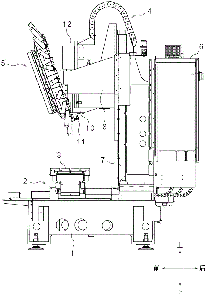
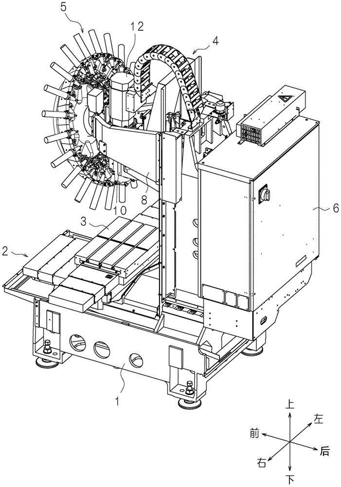
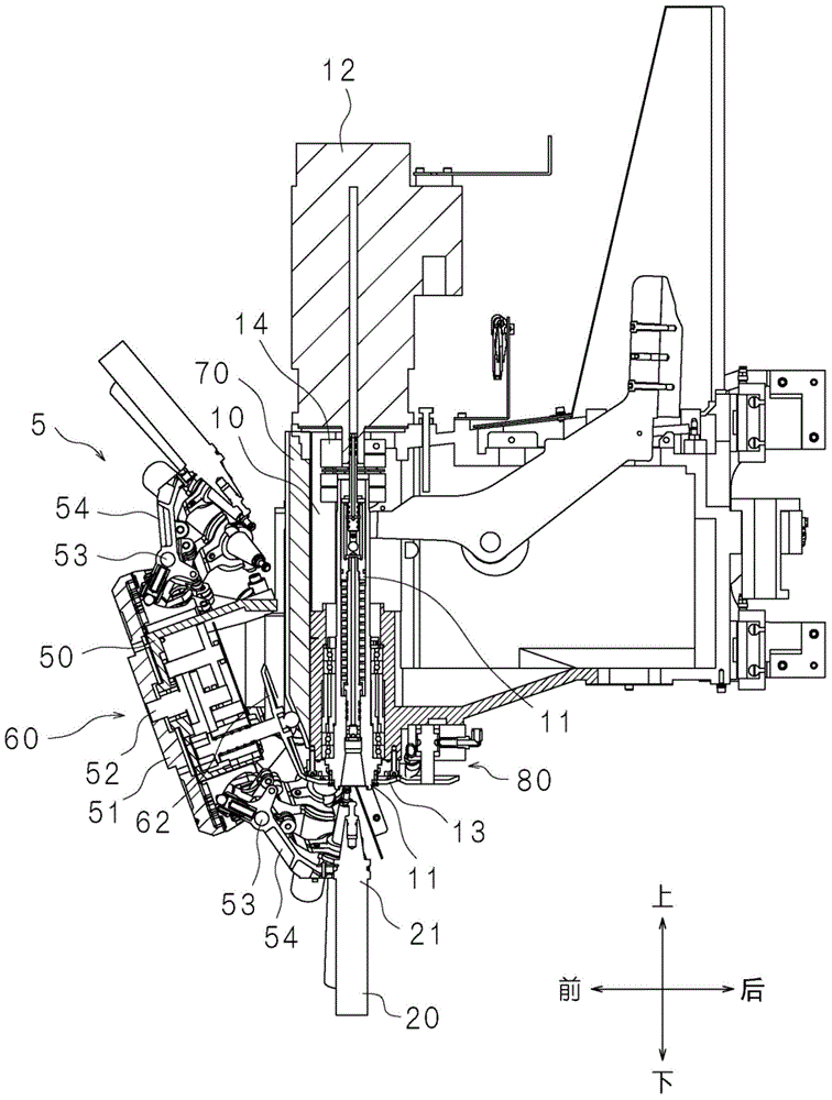
[0032] Such as figure 1 , figure 2 As shown, the machine tool includes a base 1 , an XY-axis moving device 2 , a workbench 3 , a Z-axis moving device 4 , a tool magazine 5 and a control device 6 . The XY axis moving device 2 is disposed on the upper surface of the base 1 . The workbench 3 is assembled on the XY axis moving device 2 . The table 3 moves left and right (X axis direction) and front and rear (Y axis direction) under the drive of the XY axis moving device 2 . The base 1 has uprights 7 . The column 7 extends upward behind the XY axis moving device 2 . The column 7 has a frame 8 at the top. The frame 8 extends forward on the left and right sides of the column 7 . The frame 8 supports the tool magazine 5 at the front end. The control device 6 is mounted on the rear of the column 7 . The Z-axis moving device 4 is arranged on the front part of the column 7 . Such as image 3 As shown, the Z-axis displacement device 4 is provided with a spindle head 10 at the f...
Embodiment approach 2
[0048] Such as Figure 8 As shown, the machine tool according to Embodiment 2 has a restricting device 90 . The restricting device 90 has a rotation gear 91 (engagement gear), a shaft 92 and a support body 95 . The shaft 92 has a coaxial large-diameter portion 92a. The diameter of the large-diameter portion 92 a is larger than the diameter of other portions of the shaft 92 . The large-diameter portion 92 a is accommodated in an accommodation chamber 95 a provided in the support body 95 . The accommodation chamber 95a has bearings 94 on the upper and lower sides of the large-diameter portion 92a, respectively. Each bearing 94 supports the shaft 92 . The shaft 92 is rotatable about an axis in the vertical direction. The lower end portion of the shaft 92 protrudes below the support body 95 . The rotary gear 91 is fitted to the lower end of the shaft 92 . The rotary gear 91 rotates together with the shaft 92 . The large-diameter portion 92a has a plurality of concave porti...
Embodiment approach 3
[0054] Such as Figure 11 As shown, the machine tool according to Embodiment 3 has a restricting device 90A. The restricting device 90A includes a rotation gear 91A (engagement gear), a shaft 92A, and a support body 95A. The shaft 92A has a coaxial large-diameter portion 92Aa and a middle-diameter portion 92Ac. The diameter of the large-diameter portion 92Aa is larger than the diameter of the middle-diameter portion 92Ac. The diameter of the middle diameter portion 92Ac is larger than the diameter of the portion of the shaft 92A other than the large diameter portion 92Aa and the middle diameter portion 92Ac. The large-diameter part 92Aa and the middle-diameter part 92Ac are housed in a storage chamber 95Aa provided in the support body 95A. The accommodation chamber 95Aa has bearings 94 above the large-diameter portion 92Aa and below the middle-diameter portion 92Ac. Two bearings 94 support the shaft 92A. The shaft 92A is rotatable about an axis in the vertical direction. ...
PUM
 Abstract
Description
Claims
Application Information
 - R&D
- Intellectual Property
- Life Sciences
- Materials
- Tech Scout
- Unparalleled Data Quality
- Higher Quality Content
- 60% Fewer Hallucinations
Browse by: Latest US Patents, China's latest patents, Technical Efficacy Thesaurus, Application Domain, Technology Topic, Popular Technical Reports.
© 2025 PatSnap. All rights reserved.Legal|Privacy policy|Modern Slavery Act Transparency Statement|Sitemap|About US| Contact US: help@patsnap.com