
A preheating circuit for magnetron filament

A technology for preheating circuits and magnetrons, which is applied to circuits, discharge tubes, electrical components, etc., can solve the problems of long preheating time, high cost, and the filament does not fully conform to the magnetron, and achieves fast preheating time. , the effect of constant current output

Active Publication Date: 2017-01-04
GLORYMV ELECTRONICS
View PDF3 Cites 0 Cited by
  • Summary
  • Abstract
  • Description
  • Claims
  • Application Information

AI Technical Summary

Problems solved by technology

[0006] 1. In terms of volume, the front-end voltage stabilizing device and the step-down transformer will make the entire power supply larger in size and at the same time bring higher costs;
[0007] 2. In the preheating stage, since the filament impedance of the magnetron is almost 0, when it is preheated with constant voltage, the impact current will be above 10A, which has a great impact on the life of the filament ;
[0008] 3. When preheating, you must wait until the filament current drops to a certain level before proceeding to the next shift to preheat. Usually, the preheating time required by this kind of magnetic filament power supply is about 15 minutes to reach the standard of the filament power supply. Weighing, long warm-up time;
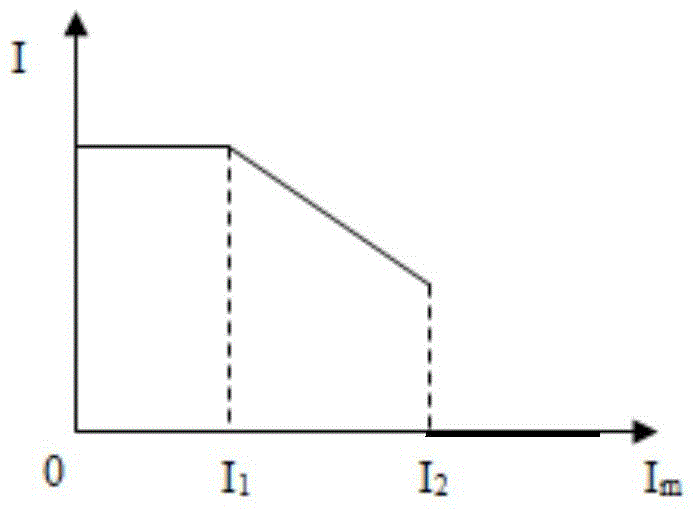
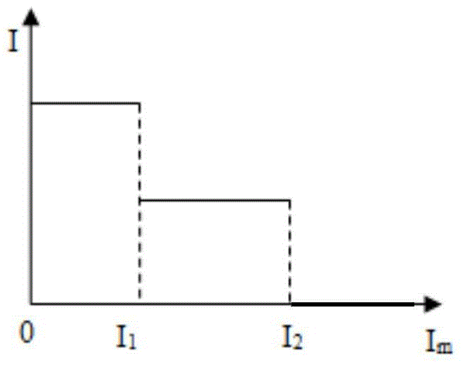
[0009] 4. In the filament unwinding stage, the filament unloading according to the gear does not fully meet the requirements of the datasheet of the magnetron manufacturer. The usually required filament unwinding curve is shown in Figure 1(a), and the filament unloading method is used to skip gears The curve of is shown in Figure 1(b), it can be seen that there is a gap between the two

Method used


Image

  • A preheating circuit for magnetron filament
  • A preheating circuit for magnetron filament
  • A preheating circuit for magnetron filament

Examples


Embodiment Construction

[0016] Referring to the accompanying drawings, through the description of the embodiments, the specific embodiments of the present invention include the shape, structure, mutual position and connection relationship of each part, the function and working principle of each part, and the manufacturing process of the various components involved. And the method of operation and use, etc., are described in further detail to help those skilled in the art have a more complete, accurate and in-depth understanding of the inventive concepts and technical solutions of the present invention.

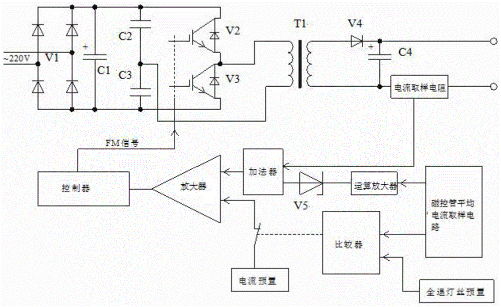
[0017] A magnetron filament preheating circuit, the power supply of this circuit adopts switching power supply inverter technology, which can be directly input from the mains ~ 220V, without the need for voltage stabilizing equipment, after the mains is input, it is rectified and filtered to form a DC bus voltage of about 300V , and then use the bridge inverter technology to adjust the inverter freque...


PUM


Abstract

The invention relates to a preheating circuit of a magnetron filament. A first rectification filter circuit, an inverter power supply circuit, a transformer T1 and a second rectification filter circuit are arranged between an input end and an output end of a power supply of the preheating circuit in turn; the inverter power supply circuit comprises a capacitor C2, a capacitor C3, a diode V2 and a diode V3; the capacitor C2 and the capacitor C3 are connected with the diode V2 and the diode V3 in a parallel mode respectively after being connected in series; a feedback regulation circuit is arranged between an output end of the second rectification filter circuit and the inverter power supply circuit; the feedback regulation circuit comprises a current sampling resistor, a controller and a first amplifier; the error amplification is performed on the sampling current of the current sampling resistor and a preset benchmark of the power supply through the first amplifier; a frequency modulation signal is given to the V2 and the V3 according to the output of the first amplifier so as to enable the current on a magnetron to be output according to a given preset value. According to the preheating circuit of the magnetron filament, the output current is detected to serve as the input of a feedback regulation power supply so as to enable the output current to be controlled within a range.

Description

technical field [0001] The invention relates to a preheating circuit of a magnetron filament, in particular to a non-jumping filament unwinding circuit. Background technique [0002] With the development of science and technology, accelerators are widely used in military, medical, industrial and other fields. As a device for generating microwaves, the magnetron plays an important role in the system of small and medium accelerators. However, the accelerator is very expensive due to its complex manufacturing process, and its life is closely related to the quality of the magnetron filament power supply. [0003] The magnetron needs to be preheated before working, and its characteristic is that the filament impedance is almost 0Ω in the cold state, and as the preheating process proceeds, the filament impedance will slowly increase to about 1Ω and remain constant (magnetron Typical value is 8.5V / 9A after the filament warm-up is complete). When the magnetron is working at high ...

Claims


Application Information

Patent Timeline
Patent Type & Authority Patents(China)
IPC IPC(8): H01J23/34
CPCH01J23/34
Inventor 王有利宫龙刘林程辉朱作敏
Owner GLORYMV ELECTRONICS
Learn More