
Crane hoisting mechanism brake balance compensation device and brake composed thereof

A lifting mechanism and balance compensation technology, applied in the direction of brake types, drum brakes, hoisting devices, etc., can solve the problems of aggravating the wear of brake pads and brake wheels 25, inconsistent relative positions, and affecting braking effects, etc. , to achieve the effect of reducing maintenance frequency, improving work reliability, and avoiding untimely adjustment

Active Publication Date: 2015-05-13
新疆天筑建工集团有限公司
View PDF5 Cites 0 Cited by
  • Summary
  • Abstract
  • Description
  • Claims
  • Application Information

AI Technical Summary

Problems solved by technology

[0004] When the screw adjustment is too short, the brake block and the brake wheel 25 cannot be completely separated when the brake is turned on, that is, the upper part of the brake block is always in contact with the brake wheel 25, causing early wear, eccentric wear and even influence on the brake block. brake effect
[0005] Secondly, because the brake block and the brake arm are hinged, the fit between the pin shaft and the hole is a clearance fit. When the brake is opened, the brake block is supported by the adjusting screw, and the maximum gap between the hinge shaft and the hinge hole appears at ( Figure 9 ) within the range of 90 degrees, and the maximum gap between the hinge shaft and the hinge hole appears in ( Figure 10 ) within the range of 90 degrees shown in ), the relative positions of the two are inconsistent, which is equivalent to reducing the effective stroke of the brake opening, making the brake opening incomplete, aggravating the wear of the brake block and the brake wheel 25, and affecting the braking effect

Method used


Image

  • Crane hoisting mechanism brake balance compensation device and brake composed thereof
  • Crane hoisting mechanism brake balance compensation device and brake composed thereof
  • Crane hoisting mechanism brake balance compensation device and brake composed thereof

Examples


Embodiment 1

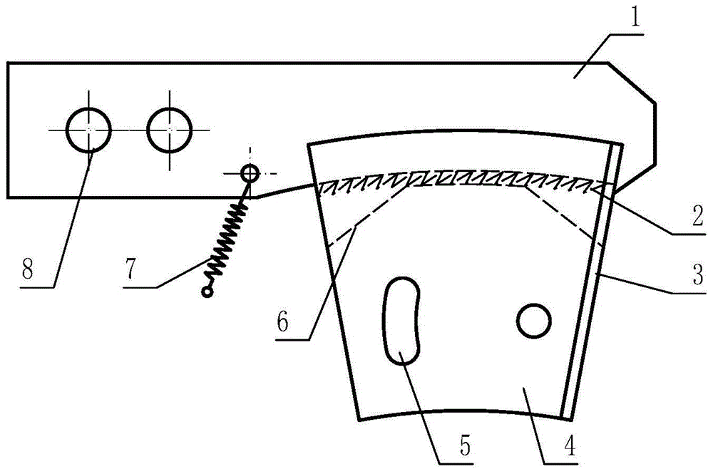
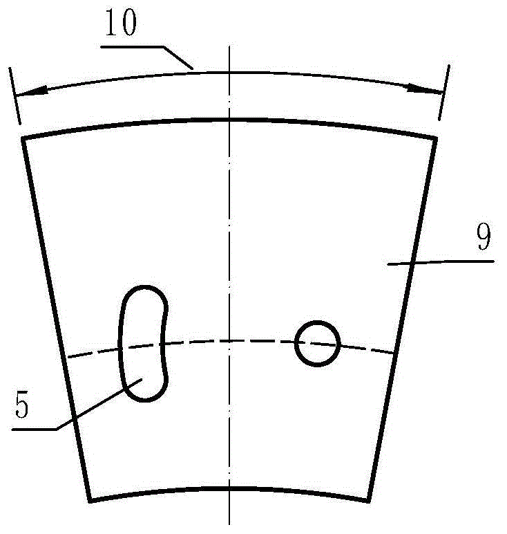
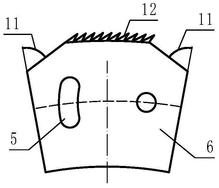
[0045] refer to figure 1 — Figure 6 , a brake balance compensation device for a crane hoisting mechanism, is characterized in that it mainly includes an arc rack 1, a sector ring tooth 6, a sector ring tooth splint 9, a sector ring tooth outer splint 4, and a tension spring 7, and the arc tooth The bar 1 is provided with sawtooth I2, the end of the curved rack 1 is provided with a hinge shaft hole 8, and the fan ring tooth 6 is provided with a sawtooth meshing with the serrated I2 provided on the curved rack 1 II12, the arc-shaped rack 1 and the sector ring teeth 6 are engaged with each other, the sector ring teeth 6 are sandwiched between the sector ring tooth splint 9 and the sector ring tooth outer splint 4, the sector ring teeth 6, The fan ring tooth splint 9 and the fan ring tooth outer splint 4 are provided with installation holes I5, the fan ring teeth 6, the fan ring tooth splint 9, and the fan ring tooth outer splint 4 are fixedly connected through the installation...

Embodiment 2

[0048] Compared with Embodiment 1, the difference of this embodiment is that: the fan ring teeth 6, the fan ring tooth splint 9, and the fan ring tooth outer splint 4 are all fan-shaped surfaces, and the angle A10 formed by the fan-shaped surfaces is 21 degrees.

Embodiment 3

[0050] Compared with Embodiment 2, the difference of this embodiment is that: the fan-shaped face of the sector ring tooth 6 is symmetrically provided with two cut corners, and the angle B11 formed by the cut corners is 63 degrees.


PUM


Abstract

The invention relates to building construction machinery and provides a tower crane hoisting mechanism brake automatic balance compensation device. The crane hoisting mechanism brake balance compensation device comprises an arc-shaped rack, sector ring teeth, a sector ring tooth clamping plate, a sector ring tooth outer clamping plate and a tension spring. The arc-shaped rack is provided with sawteeth I. The sector ring teeth are provided with sawteeth II meshed with the sawteeth I on the arc-shaped rack. The sector ring teeth are clamped between the sector ring tooth clamping plate and the sector ring tooth outer clamping plate. A crane hoisting mechanism brake composed of the balance compensation device comprises a brake releaser, a hydraulic oil cylinder, two groups of brake arms, brake arm torque springs, two groups of brake blocks and adjusting screws. The two groups of brake blocks are hinged to the two groups of brake arms through articulated shafts II respectively. The crane hoisting mechanism brake further comprises the balance compensation device. The crane hoisting mechanism brake balance compensation device greatly improves the operating reliability and durability of a hoisting mechanism brake system, reduces the maintaining frequency of the brake system and is simple in structure, economical and practical.

Description

technical field [0001] The invention relates to building construction machinery, in particular to an automatic balance compensation device for a brake of a hoisting mechanism of a tower crane. Background technique [0002] The braking device of the hoisting mechanism of the ordinary tower crane is a hydraulic push rod tile type normally closed brake. When working, the thrust of the hydraulic push rod is used to complete the opening of the brake, and the tension of the brake arm torque spring completes the closing of the brake to complete the braking. Operation, so that the lifting mechanism completes the lifting, lowering and stopping actions. But when the traditional brake is opened, because the brake block and the brake arm are hinged, the upper end of the tile block has a tendency to be close to the brake wheel 25 under the action of gravity. [0003] The manual adjustment error is relatively large. When the screw is adjusted too long, the lower side of the brake block w...

Claims


Application Information

Patent Timeline
Patent Type & Authority Applications(China)
IPC IPC(8): F16D65/52F16D49/16B66D5/00
Inventor 聂军李宗胜石建业
Owner 新疆天筑建工集团有限公司
Learn More