
Coupling

A coupling and joint surface technology, applied in the field of mechanical parts, can solve problems such as vehicle inoperability, damage to the power box, damage to the input shaft of the power box, etc., achieve good buffering and absorption effects, avoid direct shutdown, and prevent falling off Effect

Pending Publication Date: 2019-05-07
SHAANXI JOINTARK MASCH GRP CO LTD
View PDF0 Cites 0 Cited by
  • Summary
  • Abstract
  • Description
  • Claims
  • Application Information

AI Technical Summary

Problems solved by technology

However, when the internal combustion engine is working, the output torque and speed are accompanied by vibration. The vibration will be transmitted to the power box along with the outer disk. Long-term vibration will cause damage to the power box, which is mainly reflected in the damage of the input shaft of the power box.
[0003] In order to solve this problem, nylon pins or copper pins are generally used for vibration-damping connection, but high temperature is easy to cause aging and damage of nylon, and copper is gradually worn and damaged during vibration.
Some use high couplings, but high couplings generally use natural rubber. Natural rubber is not resistant to high temperatures, so it is easy to break. Although high elastic couplings using silicone rubber can withstand higher temperatures, their strength and The weather resistance is poor, and all such connection methods have a common fatal weakness, that is, there is no sign before the damage, and the damage will directly cause the vehicle to fail to operate

Method used


Image

  • Coupling
  • Coupling
  • Coupling

Examples


Embodiment Construction

[0042] In the following description, many specific details are explained in order to fully understand this application. However, this application can be implemented in many other ways different from those described herein, and those skilled in the art can make similar promotion without violating the connotation of this application. Therefore, this application is not limited by the specific implementation disclosed below.

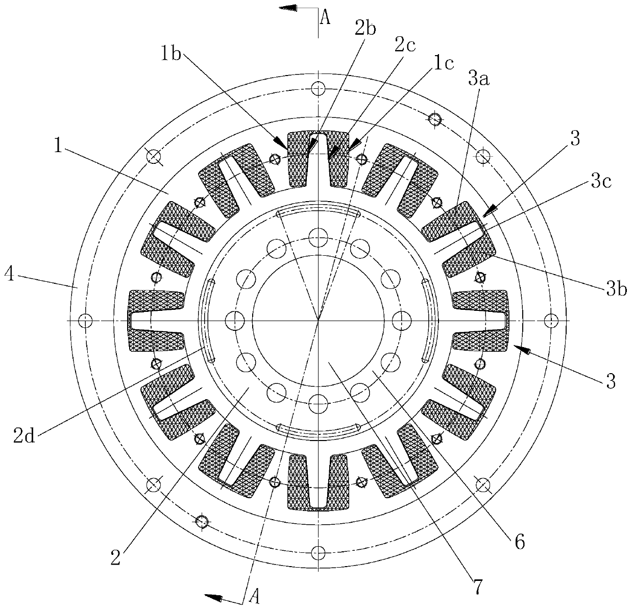
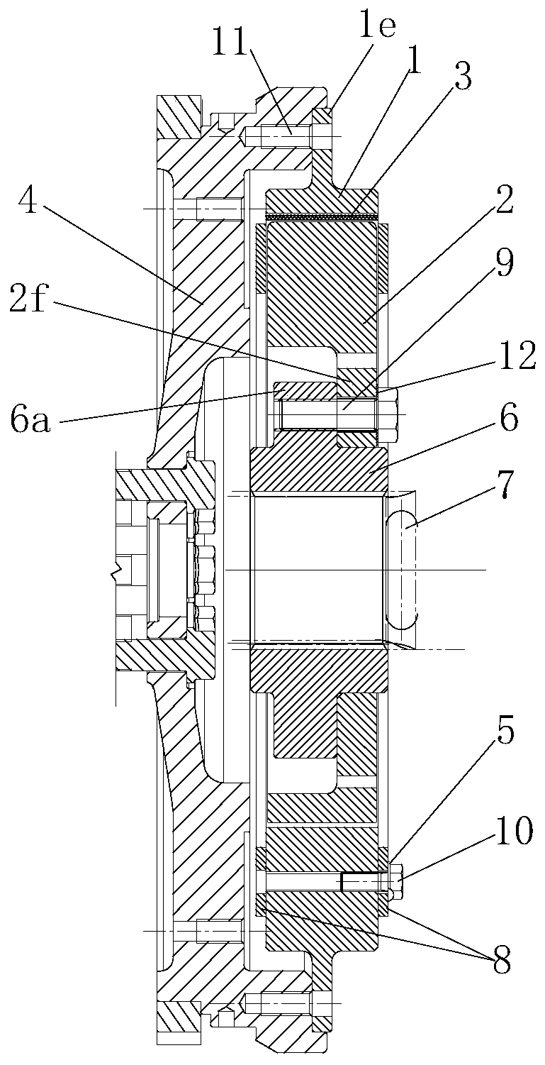
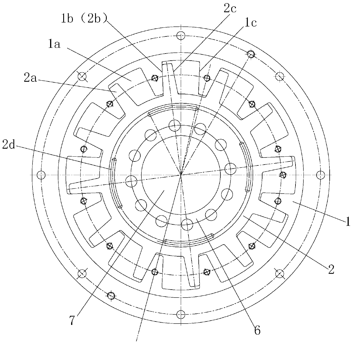
[0043] Such as figure 1 with figure 2 The coupling shown includes an external gear plate 1 for connecting with an internal combustion engine flywheel 4 to transmit torque and speed, and a power input for transmitting the torque and speed output by the external gear plate 1 to a power box. The inner toothed disk of the shaft 7, the vibration damping body 3 for absorbing the vibration of the flywheel 4 of the internal combustion engine, the damping body 3 is installed in the tooth hole 1a of the outer toothed disk 1 and the tooth 2a of the inner toothed disk 2 b...


PUM


Abstract

The invention discloses a coupling. The coupling is characterized by comprising an outer tooth disc connected with an internal combustion engine flywheel for transmitting the torque and the rotating speed, an inner tooth disc for conveying the torque and the rotating speed output by the outer tooth disc to a power input shaft of a power box body, and a damping body for absorbing vibration of the internal combustion engine flywheel; and the damping body is mounted between tooth holes of the outer tooth disc and teeth of the inner tooth disc. The coupling is simple in structure and convenient touse, can effectively absorb and buffer the vibration transferred from the internal combustion engine flywheel, and is convenient for popularization and application.

Description

Technical field [0001] The invention belongs to the technical field of mechanical parts, and specifically relates to a coupling. Background technique [0002] Construction machinery generally uses an internal combustion engine as a power source, and its flywheel is used to output torque and speed. The construction machinery power box has an input shaft. This input shaft and the flywheel are usually connected through an outer disk, that is, the flywheel will torque and speed. It is transmitted to the outer disk, and then to the input shaft of the power box through the outer disk to drive the power box to work and provide a power source for the equipment. However, the output torque and speed of the internal combustion engine are accompanied by vibration at the same time. The vibration will be transmitted to the power box along with the outer disk. Long-term vibration will cause damage to the power box, which is concentrated in the damage of the power box input shaft. [0003] In ord...

Claims


Application Information

Patent Timeline
IPC IPC(8): F16D3/12F16F15/124
Inventor 綦开隆尤畅
Owner SHAANXI JOINTARK MASCH GRP CO LTD
Learn More