
Power-on and power-off control method for electric automobile

An electric vehicle and electric control technology, applied in electric vehicles, electrical devices, vehicle components, etc., can solve problems such as user trouble, overheating damage, pre-charging resistance impact, etc., to reduce maintenance costs, improve safety factor, and avoid damage. effect of the problem

Active Publication Date: 2015-05-13
HUIZHOU EPOWER ELECTRONICS
View PDF6 Cites 23 Cited by
  • Summary
  • Abstract
  • Description
  • Claims
  • Application Information

AI Technical Summary

Problems solved by technology

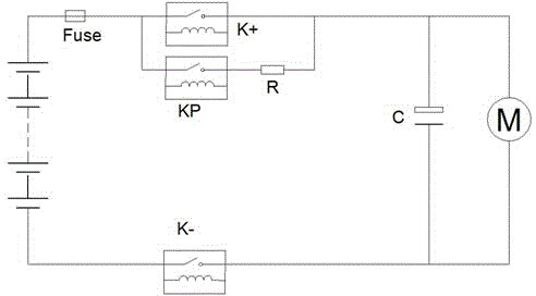
[0003] However, the above-mentioned battery system with added pre-charging circuit has the following disadvantages: the pre-charging resistor is selected according to the parameters such as the total voltage of the high-voltage circuit and the motor capacitance. Damaged by charging resistance
However, if the operator performs frequent power-on and power-off operations on the electric vehicle in a short period of time (for example, within 10 seconds), the pre-charging resistor will continue to be impacted by the instantaneous current for a long time, and it will be affected by the next current before it can cool down and recover. The impact will cause overheating damage, and the damage of the pre-charging resistor will directly cause the electric vehicle to be unable to power on and run, which will bring great trouble to the user
The pre-charging resistor may be installed in the high-voltage box or battery pack of the vehicle, and some vehicle battery packs are installed at the bottom of the vehicle, so the maintenance and replacement of the pre-charging resistor will take a lot of manpower, time and cost.

Method used


Image

  • Power-on and power-off control method for electric automobile

Examples


Embodiment Construction

[0016] In order to facilitate the understanding of those skilled in the art, the present invention will be further described in detail below.

[0017] In the present invention, the strategy of combining hardware and software is used to protect the electric vehicle pre-charging resistor.

[0018] On the hardware, the temperature sensor is used to collect and detect the temperature of the pre-charging resistor, and the software monitors the temperature of the pre-charging resistor in real time during the pre-charging step of the power-on process. If the temperature exceeds the set value (generally, the set value is 120 degrees), that is Disconnect the pre-charging relay, stop power on, and protect the pre-charging resistor. At the same time, the total positive relay is also protected, and it is not allowed to close, so that the pre-charging operation can only be performed after the temperature of the pre-charging resistor drops and recovers.

[0019] At the same time, control ...


PUM


Abstract

The invention relates to a power-on and power-off control method for an electric automobile. The method includes the steps that a BMS or an automobile control unit is adopted to monitor the interval time between a received power-on instruction and a received power-off instruction; if the interval time is larger than or equal to a certain threshold value, power-on or power-off operation is carried out normally according to the control instruction; if the interval time is smaller than the certain threshold value, a high-voltage circuit is controlled to be disconnected after time delay for a period of time, and the preparation for carrying out the power-on operation again is made; if within the delay time, the BMS or the automobile control unit receives the power-on instruction or the power-off instruction, the high-voltage circuit is not disconnected, and the power-on state continues to be kept until the delay time arrives, and then the high-voltage circuit is controlled to carry out corresponding operation according to the received instruction. A precharging resistor of the high-voltage circuit of the electric automobile can be effectively protected and prevented from being damaged, the maintenance cost of the automobile is reduced, and protection of the precharging resistor plays an active role in protecting the whole high-voltage circuit of the automobile and electric equipment on the circuit.

Description

technical field [0001] The invention relates to the control field of electric vehicles, in particular to a control method for powering on and off the electric vehicle. Background technique [0002] Such as figure 1 As shown, a pre-charging circuit must be added to the electric vehicle battery system. This is because the motor controller load M carried by the battery in the battery system has a large capacitor C at the front end. When starting in a cold state, there is no charge or only a very low residual voltage on the capacitor C. When there is no pre-charge, The main relays K+ and K- are directly connected to the capacitor C. At this time, the battery voltage VB has a high voltage above 50V, and the voltage on the load capacitor C is close to 0, which is equivalent to an instantaneous short circuit. The load resistance is only the resistance of the wire and the relay contact. Much less than 20mΩ. According to Ohm's law, the loop resistance is calculated as 20mΩ...

Claims


Application Information

Patent Timeline
Patent Type & Authority Applications(China)
IPC IPC(8): B60L3/00
Inventor 刘飞文锋阮旭松王占国黄喆
Owner HUIZHOU EPOWER ELECTRONICS
Learn More