Water pressure balance structure and construction method of stilling basin bottom plate

A stilling basin bottom plate and water pressure balancing technology, which is applied in water conservancy projects, sea area engineering, coastline protection, etc., can solve problems such as poor drainage, drainage hole suction, and excessive water pressure difference between the bottom plate of the stilling basin and achieve Maintain water pressure balance and stability, automatically adjust water pressure, and ensure stability

Active Publication Date: 2016-09-21
CHINA POWER CONSRTUCTION GRP GUIYANG SURVEY & DESIGN INST CO LTD
View PDF6 Cites 0 Cited by
  • Summary
  • Abstract
  • Description
  • Claims
  • Application Information

AI Technical Summary

Problems solved by technology

However, this structure also has some defects. On the one hand, when the pulsating pressure at the front of the stilling tank is large and the scale of turbulent flow is large, the pressure difference between the upper and lower water on the bottom of the stilling tank is likely to be too large, and the drainage holes are sucked out; on the other hand , the bottom drainage blind material is easily blocked by the concrete slurry precipitated in the water flow, resulting in poor drainage or even failure, and inconvenient maintenance, which is not conducive to the stable operation of the stilling pool

Method used


Image

  • Water pressure balance structure and construction method of stilling basin bottom plate
  • Water pressure balance structure and construction method of stilling basin bottom plate
  • Water pressure balance structure and construction method of stilling basin bottom plate

Examples


Embodiment

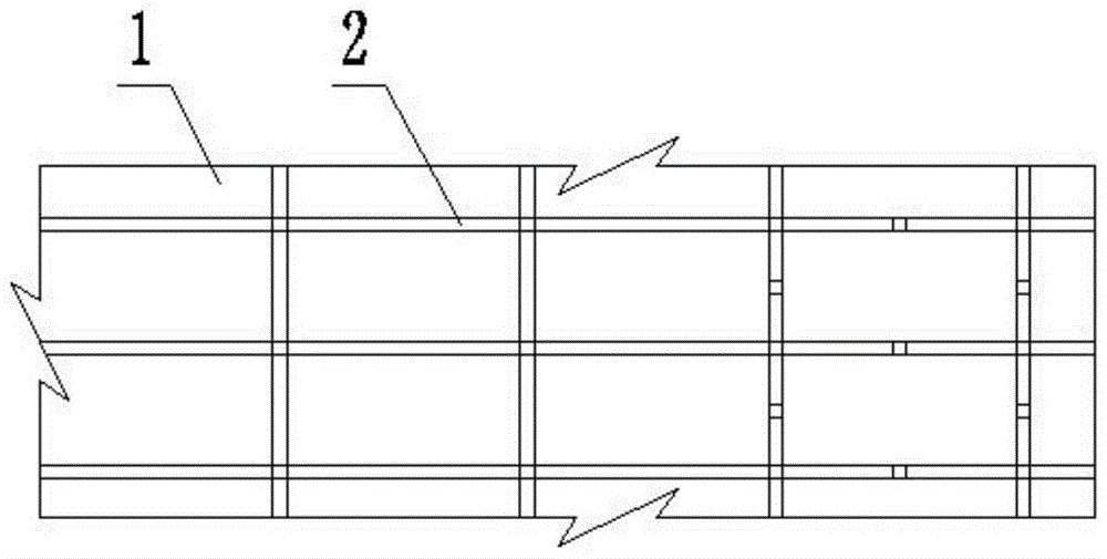
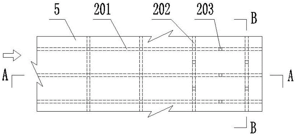
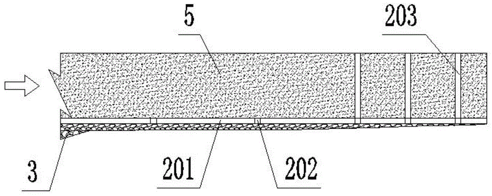
[0031] As shown in the figure, on the base surface 1 of the stilling basin, the line that needs to arrange the longitudinal drainage channel 201 and the horizontal drainage channel 202 is planned, and evenly graded crushed stones or sand pebbles are laid on the planned line and leveled; Hollow bricks 4 are laid on the layer, the direction of the through holes of the hollow bricks 4 is the same as the direction of the drainage channel, and the intersection of the longitudinal drainage channel 201 and the horizontal drainage channel 202 is filled with crushed stones or sand pebbles with uniform distribution, so that the vertical drainage channel 201 It communicates with the brick inner hole of the horizontal drainage channel 202; the outer surface of the vertical drainage channel 201 and the horizontal drainage channel 202 except the bottom surface is wrapped with polyethylene plastic film 6, so as to prevent the grout in the concrete from being separated from the hollow brick 4 w...


PUM


Abstract

The invention discloses a stilling pool base plate hydraulic pressure balance structure and a construction method thereof, and belongs to the technical field of water resources and hydropower Engineering. The stilling pool base plate hydraulic pressure balance structure and the construction method thereof comprises a stilling pool foundation surface, drainage outlets and a stilling pool base plate; the drainage outlets are distributed between the stilling pool foundation surface and the stilling pool base plate and among the stilling pool base plate; the drainage outlets comprise longitudinal drainage outlets, transverse drainage outlets and vertical drainage outlets; the longitudinal drainage outlets, the transverse drainage outlets and the vertical drainage outlets are all communicated with each other; graded broken stones also are arranged between the stilling pool base plate and the stilling pool foundation surface. According to the technical scheme, the drainage outlets formed by hollow bricks staggering in longitudinal, transverse, and vertical directions are arranged between the stilling pool base plate and the stilling pool foundation surface and among the stilling pool base plate, and the interior and the exterior of the stilling pool base plate are communicated with each other and therefore water from the stilling pool base plate can successfully discharge, the uplift pressure under the base plate is reduced, differences in pressure between the interior and the exterior of the base plate is close or equal, and the stability of the stilling pool base plate is ensured effectively.

Description

technical field [0001] The invention belongs to the technical field of water conservancy and hydropower engineering, and relates to a stilling pool system with high flood discharge intensity and high dynamic water pressure, in particular to a stilling pool floor water pressure balance structure and a construction method thereof. Background technique [0002] A stilling basin is an energy dissipation device that promotes an underflow hydraulic jump downstream of a discharge structure. The stability of the bottom plate structure of the stilling basin is related to the energy dissipation effect of the discharged water flow and whether the hydraulic structures can operate safely and stably. It is an important technology in the field of water conservancy and hydropower engineering design. The floor of the stilling basin is impacted by high-speed water flow, base uplift pressure, pulsating pressure, etc., which may cause irregular uplift and vibration of the bottom plate of the st...

Claims


Application Information

Patent Timeline
Patent Type & Authority Patents(China)
IPC IPC(8): E02B8/06
CPCE02B8/06
Inventor 李波赵继勇雷有栋崔进居浩
Owner CHINA POWER CONSRTUCTION GRP GUIYANG SURVEY & DESIGN INST CO LTD
Why Eureka
Try Eureka