A Method for Optimizing the Flow Field of a Medium-Speed ​​Mill

An optimization method and flow field technology, applied in grain processing and other directions, can solve the problems of low separation efficiency of the upper flow field, low separation efficiency, large system resistance, etc. The effect of increasing internal resistance

Active Publication Date: 2017-05-10
SHANGHAI YIFENG ELECTRICAL & MECHANICAL TECH DEV
View PDF6 Cites 0 Cited by
  • Summary
  • Abstract
  • Description
  • Claims
  • Application Information

AI Technical Summary

Problems solved by technology

However, the formed flow field has not changed substantially, the separation efficiency is still very low, and the system resistance is greater than that of traditional dynamic separators
[0022] Through the above analysis, it can be seen that whether it is a static medium-speed mill, a dynamic medium-speed mill or a combination of dynamic and static medium-speed mills, the separation efficiency of the upper flow field is relatively low, and needs to be further optimized and improved.

Method used


Image

  • A Method for Optimizing the Flow Field of a Medium-Speed ​​Mill
  • A Method for Optimizing the Flow Field of a Medium-Speed ​​Mill
  • A Method for Optimizing the Flow Field of a Medium-Speed ​​Mill

Examples


Embodiment Construction

[0049] The specific embodiments provided by the present invention will be described in detail below in conjunction with the accompanying drawings.

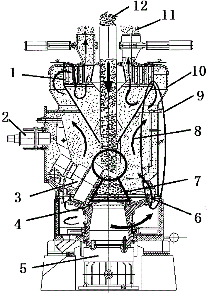
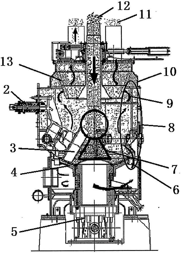
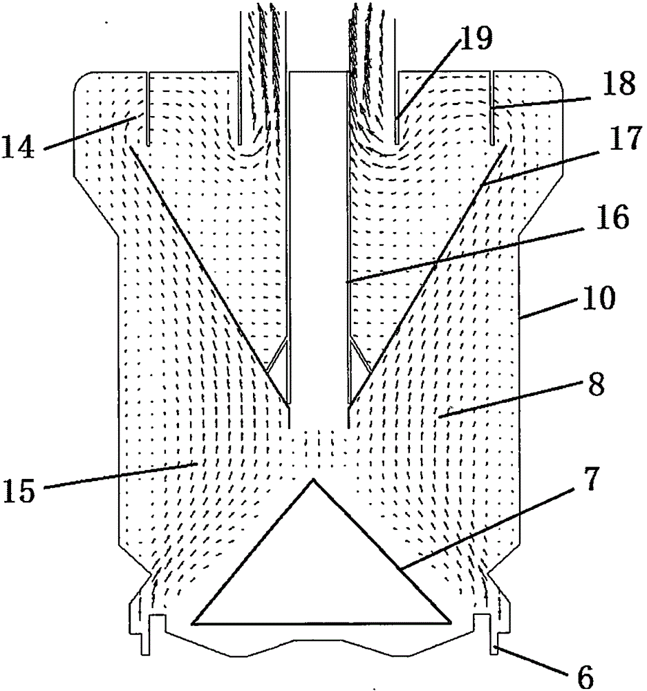
[0050] The reference signs and components involved in the accompanying drawings are as follows:

[0051] 1-Raymond separator; 2-spring loading device; 3-roller device; 4-disc device; 5-main reducer and motor; 6-annular gap; 7-inert area; Powder conveying and drying module; 10-mill shell; 11-outlet abrasive powder; 12-incoming mill material; 13-traditional dynamic separator; 14-upper flow field; 15-lower flow field; 16-central feed Tube; 17-inner cone; 18-radial blade; 19-exit pipe; 20-rotating airflow; 21-rotating leaf cage; 22-rotating airflow inside leaf cage; 23-rotating airflow outside leaf cage; 24-disc center Air inlet; 25-the airflow of the center air inlet of the millstone; 26-the material layer of the millstone; 27-the airflow of the air inlet pipe above the millstone; 28-the air inlet pipe above the millstone; 29-the air ...


PUM


Abstract

The invention provides a medium-speed abrasive flow field optimization method. The method comprises the following steps: improving a powder conveying and drying module in a medium-speed mill, and adding a millstone center air inlet, a millstone upside inlet pipe and a central air inlet pipe on the original basis of the powder conveying and drying module, so that the lower flow field in the medium-speed mill can fill all the space in the mill, an original inertia area is completely activated, and the lower flow field in the medium-speed mill is optimized; and taking a dynamic rotary separator as a separator of a powder separation module, and improving the structure of a rotor body of the dynamic rotary separator, so that hot air can form a strong spiral ascending flow field between the rotor body and a mill shell, a strong centrifugal separation effect can be achieved by the formed upper flow field, and the upper flow field in the medium-speed mill is optimized. Compared with a traditional medium-speed mill, the medium-speed mill optimized by the method disclosed by the invention has the advantages that the flow field in the mill is more reasonable, so that the overall performance of the medium-speed mill is substantially improved compared with that of the traditional medium-speed mill.

Description

[0001] 【Technical field】 [0002] The invention relates to the technical field of powder making, in particular to a medium-speed mill flow field optimization method. [0003] 【Background technique】 [0004] Medium-speed mills are widely used in cement, coal-fired thermal power generation, mining, metal smelting and other industries to grind brittle materials into powder. Although compared with steel ball mills, medium-speed mills have the advantages of small size, high output, and low power consumption, but with the continuous improvement of production technology in various industries and the current continuous improvement in the requirements for energy saving and consumption reduction, the pulverization performance of medium-speed mills There is also an urgent need for improvement, especially the need to increase the output of medium-speed mills and reduce power consumption. [0005] Structure and principle of traditional medium-speed coal mill [0006] Traditional medium-sp...

Claims


Application Information

Patent Timeline
Patent Type & Authority Patents(China)
IPC IPC(8): B02C21/00
CPCB02C15/00
Inventor 陈刚李大正何锋发程华
Owner SHANGHAI YIFENG ELECTRICAL & MECHANICAL TECH DEV
Why Eureka
Try Eureka