Data receiving device and method

A data receiving device and data technology, applied in the direction of electrical components, automatic power control, etc., can solve problems such as data omission, data receiving device 100 not working normally, and audio and video content cannot be displayed correctly, and achieve the effect of avoiding interference

Active Publication Date: 2015-04-29
REALTEK SEMICON CORP
View PDF6 Cites 7 Cited by
  • Summary
  • Abstract
  • Description
  • Claims
  • Application Information

AI Technical Summary

Problems solved by technology

However, if the transmitting end and the receiving end do not agree to transmit this information, or if interference or data omission occurs during the transmission, the data receiving device 100 will not work normally, resulting in the incorrect display of audio and video content

Method used


Image

  • Data receiving device and method
  • Data receiving device and method
  • Data receiving device and method

Examples


Embodiment Construction

[0029] The technical terms in the following explanation refer to the customary terms in this technical field. If some terms are described or defined in this manual, the explanation of these terms shall be based on the description or definition in this manual.

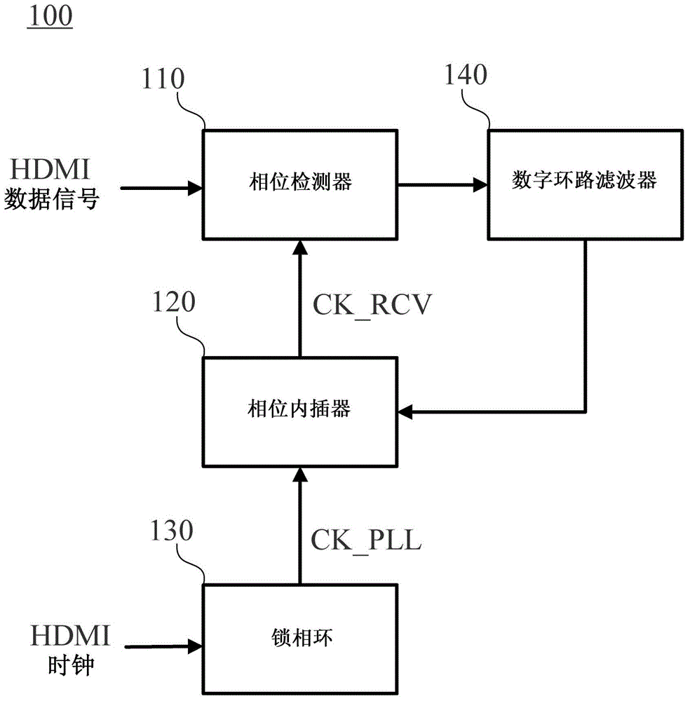
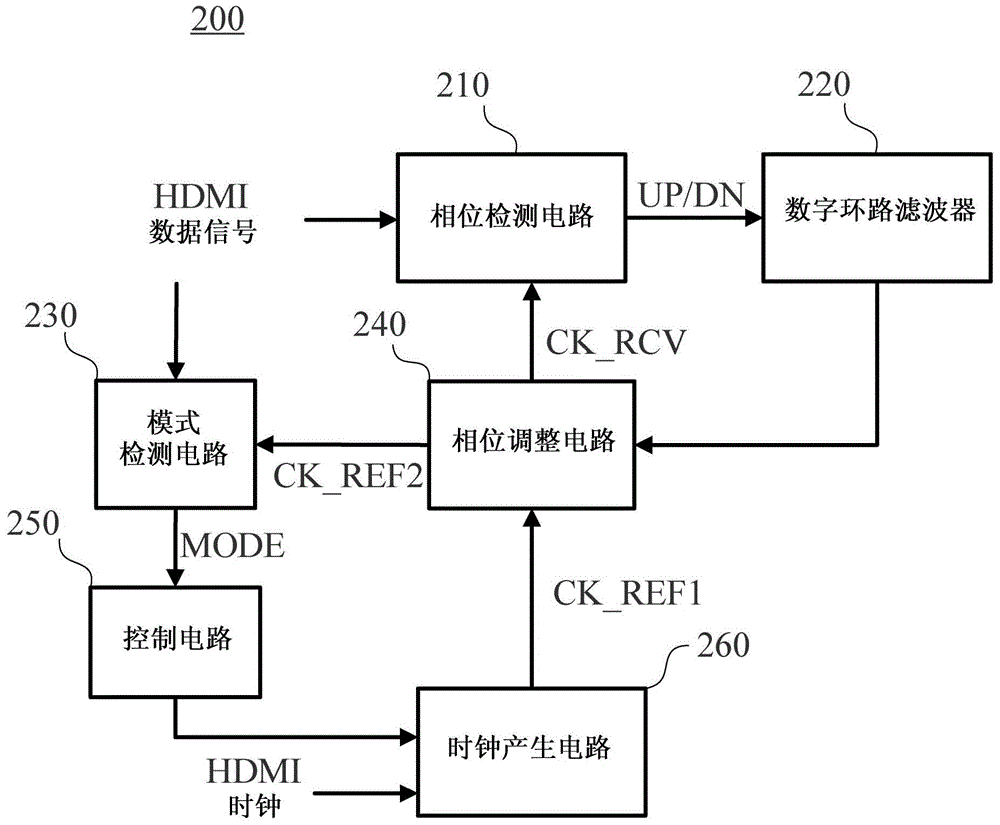
[0030]The disclosed content of the present invention includes a data receiving device and a data receiving method, which can know the transmission mode of the data signal. The device and method can be applied to the receiving end of the high-definition multimedia interface. Under the premise of possible implementation, those skilled in the art can select equivalent components or steps according to the disclosure content of this specification to realize the present invention. That is, implementation of the present invention is not limited to the embodiments described below. Since some of the components included in the data receiving device of the present invention may be known components individually, the details of the ...


PUM


Abstract

The present invention discloses a data receiving device and method, for identifying a transmitting mode to which a data signal belongs. The method comprises the following steps: according to a source clock, generating a first reference clock; according to the data signal and a data recovery clock, generating a phase detection signal; according to the phase detection signal, adjusting a phase of the first reference clock to generate a data recovery clock; according to the phase detection signal and the first reference clock, generating a second reference clock, wherein the second reference clock has the same frequency as the data recovery clock and has a phase difference; according to the second reference clock and the data signal, detecting the transmitting mode, to generate a mode signal; and according to the mode signal, determining whether to change the frequency of the first reference clock.

Description

technical field [0001] The invention relates to a data receiving device and method, in particular to a data receiving device and method of a high-definition multimedia interface. Background technique [0002] The High Definition Multimedia Interface (hereinafter referred to as HDMI) is a common audio and video transmission interface at present. see figure 1 , which is an existing data receiving device 100 applied to the receiving end of HDMI, including a phase detector (Phase Detector, PD) 110, a phase interpolator (Phase Interpolator, PI) 120, a phase locked loop (Phase Lock Loop, PLL) 130 and a digital loop filter (Digital Loop Filter) 140 . The original HDMI signal usually includes HDMI data signal and HDMI clock. The HDMI data signal contains the color data of the image; after proper processing, the HDMI clock can be used to sample the HDMI data signal to restore the color data. like figure 1 As shown, the PLL 130 refers to the HDMI clock to generate a reference clo...

Claims


Application Information

Patent Timeline
Patent Type & Authority Applications(China)
IPC IPC(8): H03L7/099
Inventor 王腾毅
Owner REALTEK SEMICON CORP
Why Eureka
Try Eureka