
Novel magnetic gear for two-way air-gap field

A technology of air-gap magnetic field and magnetic gear, which is applied in the field of magnetic gear with a new bidirectional air-gap magnetic field, can solve the problems of magnetic path difference, low transmission torque and efficiency, low torque density, etc., and achieve the elimination of friction loss and reliability High, high transmission efficiency effect

Inactive Publication Date: 2015-04-29
ZHEJIANG UNIV
View PDF6 Cites 3 Cited by
  • Summary
  • Abstract
  • Description
  • Claims
  • Application Information

AI Technical Summary

Problems solved by technology

[0003] In 2001, British scientists proposed a new magnetic gear structure based on magnetic field modulation technology, which overcomes the shortcomings of traditional magnetic gears, such as magnetic path difference, torque transmission and low efficiency, making magnetic gear technology a research hotspot in recent years.
The torque transmitted by the magnetic gear is equivalent to that of the mechanical gear. Although it has the advantages of no lubrication, low noise and automatic overload protection, it also has the disadvantages of low torque density.

Method used


Image

  • Novel magnetic gear for two-way air-gap field
  • Novel magnetic gear for two-way air-gap field
  • Novel magnetic gear for two-way air-gap field

Examples


Embodiment Construction

[0034] The present invention will be described in further detail below in conjunction with the accompanying drawings and specific embodiments.

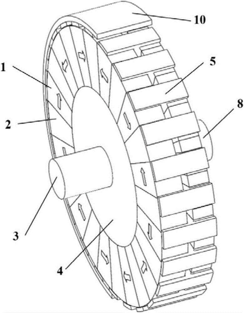
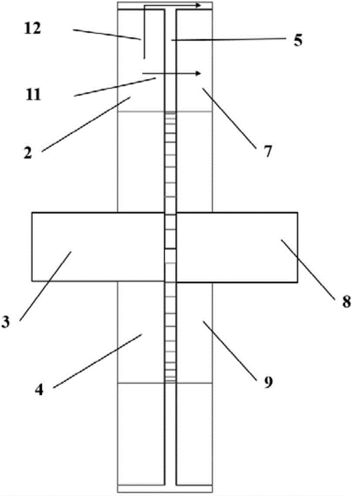
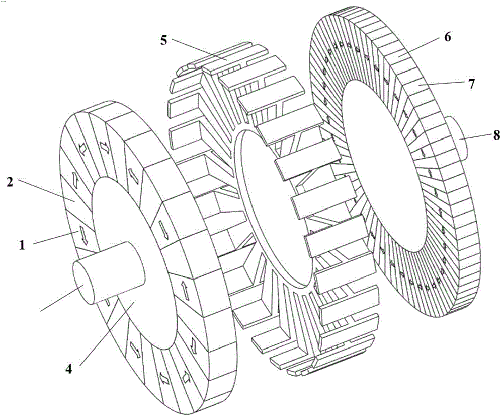
[0035] like Figure 1 ~ Figure 3 As shown, the present invention includes a stator casing 10 and a driving wheel coaxially installed in the stator casing 10, a driven wheel and a magnetic modulation grid 5, and the driving wheel and the driven wheel are respectively installed at two ends of the magnetic modulation grid 5, and the magnetic modulation The stator housing 10 is installed around the grid 5, the driving wheel and the driven wheel are both disc-shaped, there are gaps between the magnetic adjustment grid 5 and the driving wheel and the driven wheel respectively, and the center of the driving wheel inner ring 4 is provided with an input shaft 3 , P 1 For the driving wheel permanent magnet 1 of tangential magnetization, the driving wheel magnetization block 2 is installed between two adjacent driving wheel permanent magnets 1;...


PUM


Abstract

The invention discloses a novel magnetic gear for a two-way air-gap field. The novel magnetic gear for the two-way air-gap field comprises a driving wheel, a driven wheel and a magnetic field regulating grid, wherein the driving wheel and the driven wheel are coaxially mounted in a stator housing. The driving wheel and the driven wheel are arranged on the two ends of the magnetic field regulating grid respectively, and a gap is kept between the driving wheel and the driven wheel. Driving wheel permanent magnets are evenly distributed on the peripheral face of a driving wheel inner ring at intervals. Driven wheel permanent magnets are evenly distributed on the peripheral face of a driven wheel inner ring at intervals. A driven wheel assemble magnetic patch is arranged between the adjacent driving wheel and driven wheel. Magnetic field regulating teeth are arranged on the periphery of the magnetic field regulating grid inner ring. The arc lengths for both ends of the axial component of the T-shaped magnetic field regulating teeth are equal. An air-gap field forms a closed magnetic circuit through an axial direction air gap and a radical direction air gap. No-contact transmission is carried out under the interaction of the permanent magnet and the magnetic field. The novel magnetic gear for the two-way air-gap field has the advantages that transmission efficiency is high, reliability is high, abrasion caused by mechanical contact does not exist, lubrication is not needed, the isolating between an input shaft and an output shaft is achieved, and the overload protection function can be achieved. The novel magnetic gear for the two-way air-gap field can be widely used in the new energy field, such as wind power generation, electromobiles, and electrical ships and warships.

Description

technical field [0001] The invention relates to a magnetic gear, in particular to a novel magnetic gear with bidirectional air gap magnetic field, which can be widely used in new energy fields such as wind power generation, electric vehicles and ships. Background technique [0002] Traditional variable speed and variable torque widely use mechanical gearboxes, which have problems such as wear, noise, and mechanical fatigue. They have high requirements for lubrication and maintenance, and friction loss reduces system efficiency. In response to these inherent shortcomings of mechanical gears, magnetic gear technology has gained more and more attention in the past decade. [0003] In 2001, British scientists proposed a new magnetic gear structure based on magnetic field modulation technology, which overcomes the shortcomings of traditional magnetic gears, such as magnetic path difference, transmission torque and low efficiency, making magnetic gear technology a research hotspot...

Claims


Application Information

Patent Timeline
IPC IPC(8): H02K51/00
Inventor 印欣方攸同福义涛黄晓艳马吉恩张健
Owner ZHEJIANG UNIV
Learn More