
Method for making power generation plan in consideration of direct current interaction

A technology for power generation planning and planning, applied in computing, data processing applications, forecasting, etc., can solve problems such as the risk of safe and stable operation of the power grid, the impact of new energy consumption in the power grid, and the lack of safety and economy.

Active Publication Date: 2015-04-29
NARI TECH CO LTD +1
View PDF5 Cites 22 Cited by
  • Summary
  • Abstract
  • Description
  • Claims
  • Application Information

AI Technical Summary

Problems solved by technology

The cross-regional DC power transmission mode is mostly constant power transmission during peak and valley periods, because the intermittency and volatility of new energy sources are not considered, and the cross-regional DC power plan fails to fully consider the peak-shaving and backup requirements of the sending / receiving end grid and the short-term use of new energy sources. According to the power forecasting results, the cross-regional DC transmission power grid has to keep more reserves in order to meet the stable operation of DC power during the day-to-day and intra-day planning, especially in the period when the peak-shaving capacity of the power grid is tense in the low valley, which may affect the consumption of new energy in the power grid. It has a serious impact and brings potential risks to the safe and stable operation of the power grid, and there are deficiencies in both safety and economy

Method used


Image

  • Method for making power generation plan in consideration of direct current interaction
  • Method for making power generation plan in consideration of direct current interaction
  • Method for making power generation plan in consideration of direct current interaction

Examples


Embodiment Construction

[0099] The technical scheme of the present invention will be described in further detail below in conjunction with the accompanying drawings and specific embodiments, so that those skilled in the art can better understand the present invention and implement it, but the examples given are not intended to limit the present invention.

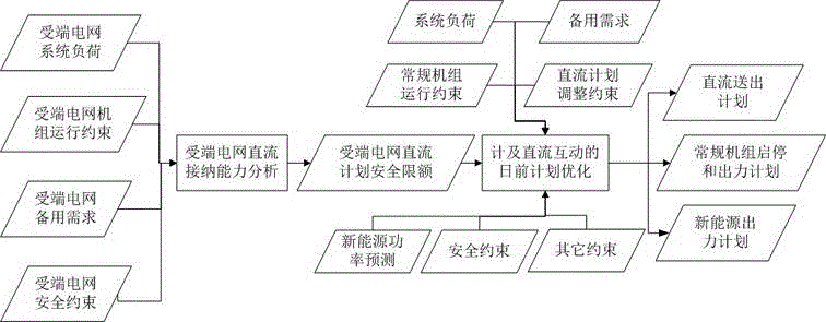
[0100] A generation planning method considering DC interaction, such as figure 1 shown, including the following steps:

[0101] 01) According to the system load demand constraints, unit operation constraints, backup demand constraints and receiving-end grid safety constraints of the DC receiving-end grid, an analysis model of the DC receiving capacity of the receiving-end grid is established with the optimization goal of maximizing and minimizing the DC input power;

[0102] 02) Calculate the maximum and minimum safety limits of the DC reception of the DC receiving power grid according to the analysis model of the DC receiving capacity of the rec...


PUM


Abstract

The invention discloses a method for making a power generation plan in consideration of direct current interaction. The method is characterized by comprising the following steps: 01) establishing a receiving-end power grid direct current receptivity analysis model taking received direct current power maximization and minimization as an optimization aim according to the system load requirement constraint, unit running constraint, standby requirement constraint and receiving-end power grid safety constraint of a direct current receiving-end power grid; 02) calculating maximum and minimum safe direct current receiving limits of the direct current receiving-end power grid according to the receiving-end power grid direct current receptivity analysis model; 03) optimally making a direct current sending plan, a new energy output plan, a conventional energy unit starting and stopping plan and an output plan of a sending-end power grid by taking new energy consumption maximization as an optimal aim by virtue of a mixed integer programming method according to the direct current receptivity constraint and direct current plan regulation constraint of the direct current receiving-end power grid and the system load requirement, standby requirement constraint, conventional unit running constraint, new energy power prediction result and sending-end power grid safety constraint of the sending-end power grid.

Description

technical field [0001] The invention relates to a generation planning method considering DC interaction. Background technique [0002] In recent years, China has vigorously developed wind power and photovoltaic power generation. According to the plan of the Chinese government, by 2015, the national wind power grid-connected capacity will reach 100GW, and the photovoltaic power grid-connected capacity will reach 35GW. However, the geographical distribution of China's energy resources is very uneven. Northwest China is rich in coal and other conventional energy sources, as well as wind power and photovoltaic power generation resources, but its economy is relatively underdeveloped. In addition, wind power and photovoltaic power generation have developed rapidly in the northwest region in recent years, and the problems of wind and solar curtailment are serious, while the eastern region is economically developed and the energy supply is relatively insufficient. [0003] In order...

Claims


Application Information

Patent Timeline
Patent Type & Authority Applications(China)
IPC IPC(8): H02J3/46G06Q10/04G06Q50/06
CPCG06Q10/04G06Q50/06H02J3/46Y04S10/50
Inventor 张慧玲涂孟夫韩红卫丁恰马军马冬冬施佳锋李婷
Owner NARI TECH CO LTD
Learn More