
Feed-in device and wave collector

A wave collector and waveguide technology, which is applied in the direction of waveguide horn, antenna grounding switch structure connection, circuit, etc., can solve the problem of inability to take into account the return loss of Ku frequency band, etc., to improve return loss, reduce return loss, and increase the degree of freedom Effect

Active Publication Date: 2017-05-10
WISTRON NEWEB
View PDF7 Cites 0 Cited by
  • Summary
  • Abstract
  • Description
  • Claims
  • Application Information

AI Technical Summary

Problems solved by technology

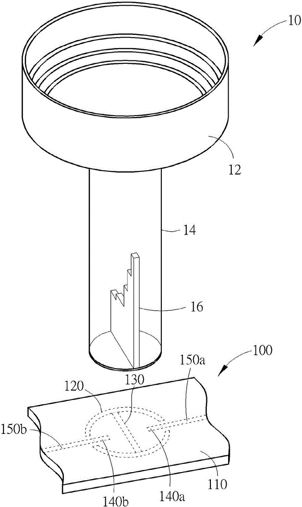
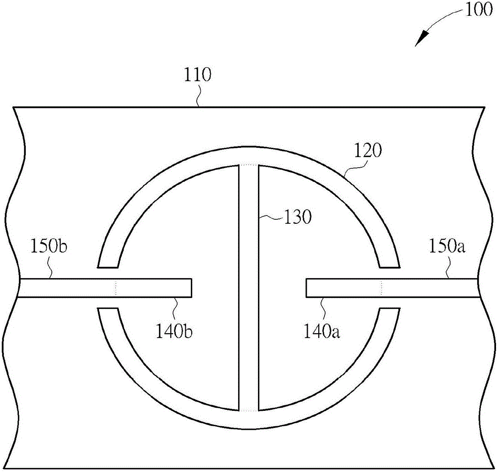
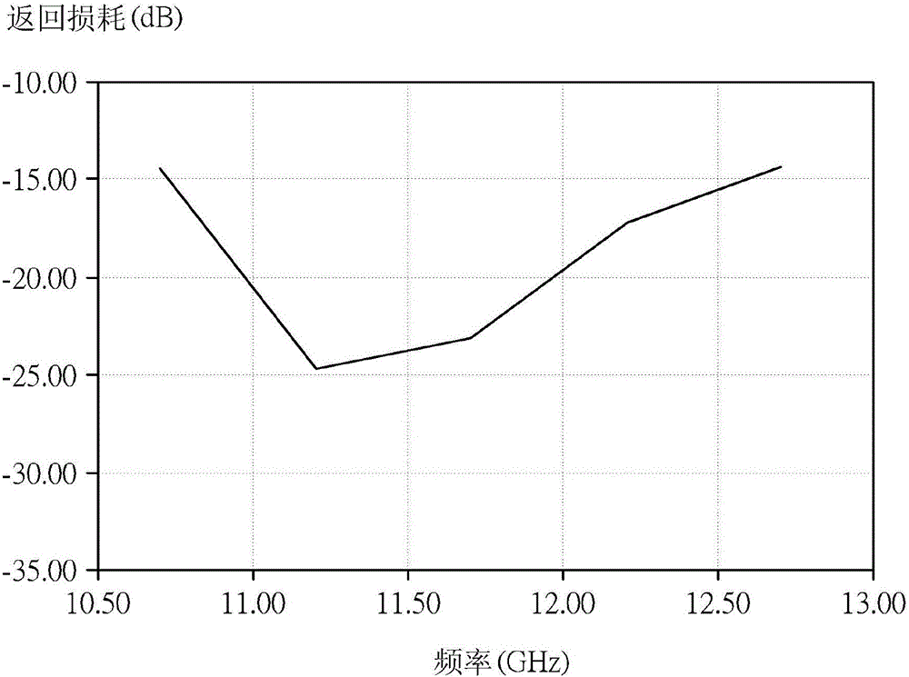
Therefore, the feed-in device 100 cannot take into account the return loss of the high frequency and low frequency parts in the Ku frequency band

Method used


Image

  • Feed-in device and wave collector
  • Feed-in device and wave collector
  • Feed-in device and wave collector

Examples


Embodiment Construction

[0055] Please refer to figure 2 , figure 2 It is a front top view of a feed-in device 20 according to an embodiment of the present invention. Feedthrough device 20 can replace Figure 1A , Figure 1B The feed-in device 100 is used for the wave collector 10 to transmit the radio frequency signal received by the horn antenna 12 to the back-end radio frequency processing unit. The feed-in device 20 includes a substrate 200, a ring-shaped ground metal sheet 202, a rectangular ground metal sheet 204, feed-in metal sheets 206, 208, signal lines 210, 212 and parasitic ground metal sheets 214, 216, wherein the ring-shaped The ground metal piece 202 , the rectangular ground metal piece 204 , the feeding metal pieces 206 , 208 , the signal lines 210 , 212 and the parasitic ground metal pieces 214 , 216 are all disposed on the substrate 200 . The ring-shaped grounding metal sheet 202 generally has a ring structure, and two notches are formed on it to divide the ring into two discont...


PUM


Abstract

The invention discloses a feed-in device and a wave collector. The feed-in device comprises a substrate, a ring earthing metal sheet, a rectangular earthing metal sheet, a first parasitic earthing metal sheet, a second parasitic earthing metal sheet, a first feed-in metal sheet and a second feed-in metal sheet, wherein the ring earthing metal sheet is approximately annular and is provided with a first notch and a second notch; the rectangular earthing metal sheet extends towards the interior of a ring from a ring earthing metal wire, and corresponds to a mounting position of a polarized sheet of a waveguide; the first parasitic earthing metal sheet extends towards a first direction from one side of a rectangular earthing metal wire; the second parasitic earthing metal sheet extends towards a second direction from the other side of the rectangular earthing metal wire; the first feed-in metal sheet extends towards the interior of the ring from the first notch and comprises a first section, a second section and a third section, widths of the first section and the second section are not equal and widths of the second section and the third section are not equal; the second feed-in metal sheet extends towards the interior of the ring from the second notch, and comprises a fourth section, a fifth section and a sixth section, and widths of the fourth section and the fifth section are not equal and widths of the fifth section and the sixth section are not equal. The feed-in device can be used for improving the impedance matching and reducing the return loss as well as increasing the design degree of freedom, and is easy to fabricate.

Description

technical field [0001] The invention relates to a feed-in device and a wave collector for a waveguide, in particular to a feed-in device and a collector that can effectively improve impedance matching at low frequencies and high frequencies and reduce return loss (Return Loss). oscilloscope. Background technique [0002] Satellite communication has the advantages of wide coverage and no interference from the ground environment. It is widely used in military, detection and commercial communication services such as satellite navigation, satellite voice broadcasting or satellite TV broadcasting. The known satellite communication receiving device is composed of a dish reflector (Dish Reflector) and a wave collector, and the wave collector is arranged at the focus position of the dish reflector, which can receive the radio wave signal reflected by the dish reflector, The radio wave signal is down-converted to an intermediate frequency, and then sent to a satellite signal process...

Claims


Application Information

Patent Timeline
Patent Type & Authority Patents(China)
IPC IPC(8): H01Q1/50H01Q13/02
Inventor 郭瞬仲詹兆凯
Owner WISTRON NEWEB
Learn More