
Diaphragm accumulator

A technology for accumulators and diaphragms, which is applied in the direction of actuator accumulators, fluid pressure actuating devices, mechanical equipment, etc., and can solve problems such as heavy weight, insufficient diaphragm installation and sealing, and inconvenient use

Inactive Publication Date: 2015-04-29
常州市安家热工仪表有限公司
View PDF0 Cites 2 Cited by
  • Summary
  • Abstract
  • Description
  • Claims
  • Application Information

AI Technical Summary

Problems solved by technology

However, in the diaphragm accumulator, there are defects such as insufficient sealing, large volume and heavy weight in the installation of the diaphragm, which is very inconvenient to use

Method used


Image

  • Diaphragm accumulator

Examples


Embodiment Construction

[0011] The present invention will be further described below in conjunction with the drawings and specific embodiments.

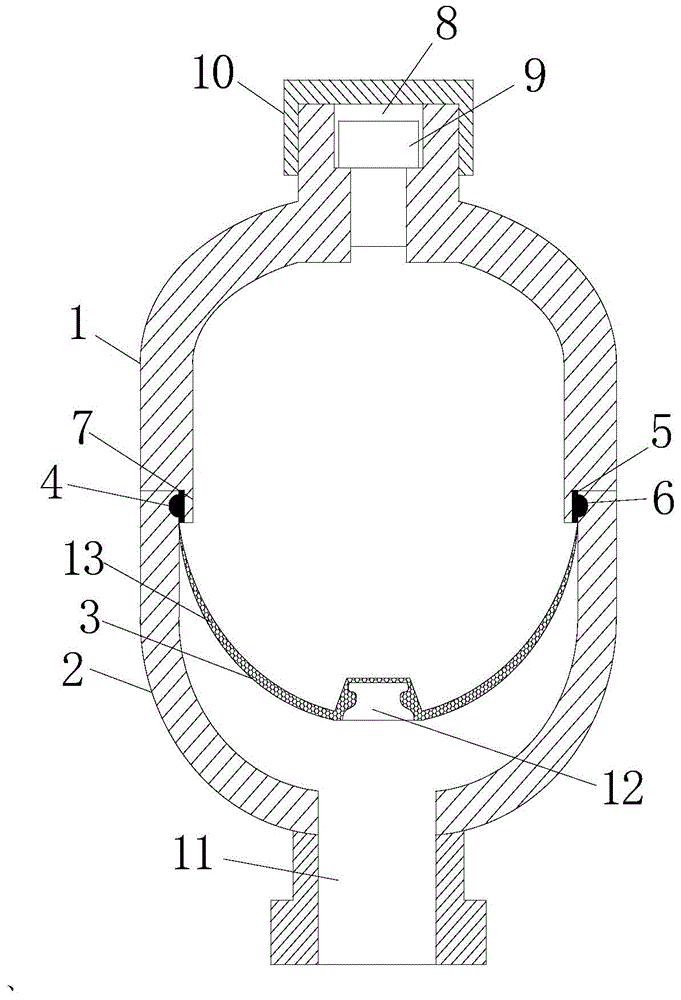
[0012] Such as figure 1 , Diaphragm accumulator, including a tank composed of an upper cover 1 and a lower cover 2, and a diaphragm 3. The inner wall of the lower cover 1 is provided with an annular groove 4, and the open end of the diaphragm 3 is tightened The part 5 is fixed in the annular groove 4, the diaphragm 3 divides the tank body into two independent air chambers and oil chambers. The fastener 5 has an annular structure, and the outer side of the fastener 5 is provided with a convex corresponding to the annular groove. From 6, the cross-section of the fastener 5 is T-shaped, and the lower end of the inner wall of the upper cover 1 is provided with a limiting ring plate 7. The outer diameter of the limiting ring plate 7 is the same as the inner diameter of the fastener 5. Covered with elastic band 13.

[0013] The upper cover body 1 and the lower cover...


PUM


Abstract

The invention relates to a diaphragm accumulator which comprises a tank body and a diaphragm, wherein the tank body is formed by connecting an upper cover body and a lower cover body; the inner wall of the lower cover body is provided with a circular groove; the opening end part of the diaphragm is fixed in the circular groove by virtue of a fastener; the interior of the tank body is divided into an air cavity and an oil cavity which are independent by the diaphragm; the fastener is of a circular structure; the outer side of the fastener is provided with a bulge which adapts to the circular groove; the section of the fastener is T-shaped; the lower end of the inner wall of the upper cover body is provided with a limit circular plate; the outer diameter of the limit circular plate is consistent with the inner diameter of the fastener; the inner layer of the diaphragm is wrapped with an elastic band. The diaphragm accumulator has the characteristics of simple structure, good sealability, small size, light weight and the like.

Description

Technical field [0001] The present invention relates to the technical field of accumulators, in particular to diaphragm accumulators. Background technique [0002] Accumulator is a hydraulic device that stores energy. It is widely used in hydraulic systems to maintain pressure, absorb pressure shocks, pressure pulses, and store energy as an auxiliary power source to compensate for pressure. Existing accumulators mostly adopt diaphragm type, piston type, spring type, etc. However, in the diaphragm type accumulator, the installation of the diaphragm has defects such as insufficient sealing, large volume and heavy weight, which is very inconvenient to use. Summary of the invention [0003] In view of the above-mentioned problems, the object of the present invention is to provide a diaphragm accumulator with simple structure, good sealing performance, small volume and light weight. [0004] The technical scheme for realizing the present invention is as follows: [0005] The diaphragm a...

Claims


Application Information

Patent Timeline
Patent Type & Authority Applications(China)
IPC IPC(8): F15B1/04
CPCF15B1/04F15B2201/3151F15B2201/405
Inventor 袁志东
Owner 常州市安家热工仪表有限公司
Learn More