Eureka AIR delivers breakthrough ideas for toughest innovation challenges, trusted by R&D personnel around the world.

Movable loading frame

A material rack and movable rod technology, which is applied in the field of movable material racks, can solve the problems of high construction cost, affecting the construction period, time-consuming and labor-intensive inner wall of the material rack storage tank, etc., so as to save construction time, improve construction efficiency, and facilitate transfer Effect

Inactive Publication Date: 2015-04-29
CHONGQING JUKANG BUILDING MATERIAL
View PDF0 Cites 0 Cited by
  • Summary
  • Abstract
  • Description
  • Claims
  • Application Information

AI Technical Summary

Problems solved by technology

[0003] The purpose of the present invention is to solve the problem of time-consuming and labor-intensive work on the inner wall of the storage tank on the existing loading rack, which affects the progress of the construction period and the problem of high construction costs

Method used


Image

  • Movable loading frame
  • Movable loading frame

Examples


Embodiment Construction

[0013] Below in conjunction with accompanying drawing and embodiment the technical solution of the present invention is further described:

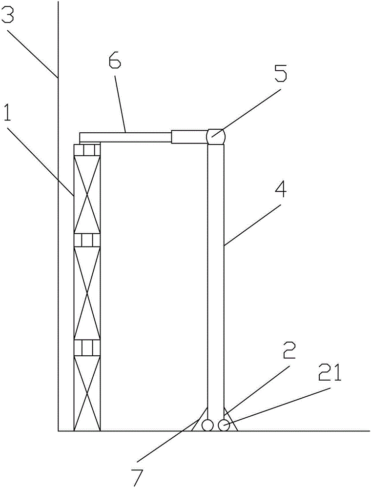
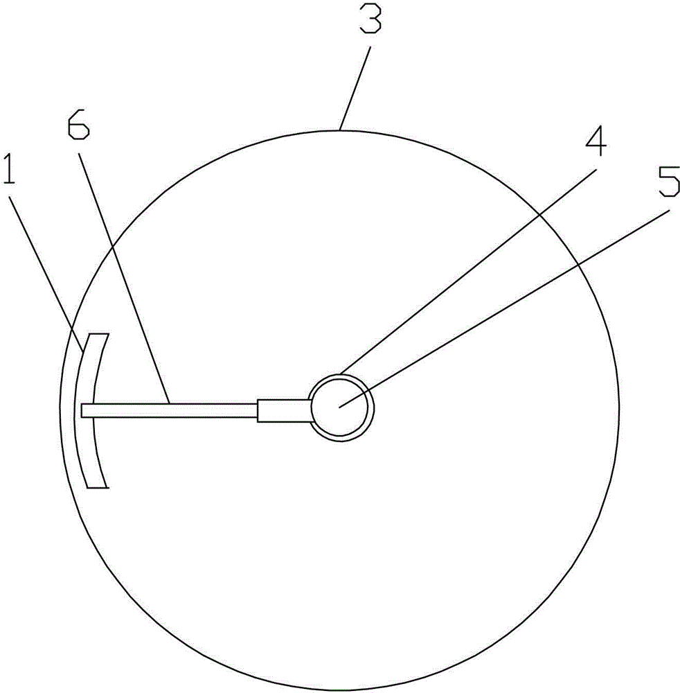
[0014] Such as figure 1 and figure 2 As shown, the present invention provides a movable feeding rack, comprising a feeding rack frame body 1, a movable device 2 is installed at the bottom of the feeding rack frame body 1, and a telescopic support rod 4 arranged in a storage tank 3 is also included , the rotary drive device 5 located at the top of the telescopic support rod 4, the movable rod 6, one end of the movable rod 6 is fixedly connected with the rotary drive device 5, and the other end is fixedly connected with the upper part of the feeding rack frame body 1, and the movable device 2 comprises a roller 21, and the periphery of the roller 21 is provided with a positioning plate 7, and the positioning plate 7 is two pieces. In addition, a protective cover is provided on the periphery of the feeding rack frame body 1, four mobile d...


PUM


Abstract

The invention belongs to the field of building material processing, in particular relates to a movable loading frame which comprises a loading frame body. The bottom of the loading frame body is provided with a movable device, and the movable loading frame further comprises a retractable supporting pole arranged in a storage tank, a rotation driving device arranged at the top end of the retractable supporting pole and a movable pole. One end of the movable pole is connected with the rotation driving device and the other end of the movable pole is connected with the upper part of the loading frame body. The movable device comprises an idler wheel. The periphery of the idler wheel is provided with at least two location plates. According to the movable loading frame of the technical scheme of the invention, the problems that the operation of the storage tank inner wall of the existing loading frame wastes time and energy, the project progress is influenced and the construction cost is high are solved.

Description

technical field [0001] The invention belongs to the field of building material processing, and in particular relates to a movable feeding rack. Background technique [0002] Cement is a commonly used building material. In the manufacturing process, building material raw materials are put into the storage tank through the loading rack. The traditional loading rack is a fixed structure, which is removed after construction. During the production and installation of large storage tanks, the anti-corrosion project of the inner wall of the storage tank is essential, and on the construction site, a full-scale feeding rack is basically built along the inner wall of the storage tank to meet the needs of construction. Its disadvantages are: the erection of full-room loading racks is time-consuming and laborious, which affects the construction period; the installation cost is high. Since the area of ​​full-room loading racks in large storage tanks is generally several hundred square me...

Claims


Application Information

Patent Timeline
IPC IPC(8): E04G1/36E04G1/24
Inventor 张信聪
Owner CHONGQING JUKANG BUILDING MATERIAL
Why Eureka
Eureka Blog
Learn More