Automatic submersible motor copper end ring casting machine

A technology for submersible motors and copper end rings, applied in the direction of casting molds, casting mold components, casting molding equipment, etc., can solve the problems of copper end ring production that cannot be completely solved, does not meet the electromagnetic requirements of the motor squirrel cage, and cannot perfectly meet the process requirements and other problems, to achieve the effect of small strain force, low cost, and not easy to deform

Active Publication Date: 2015-04-29
SHANXI TIANHAI PUMP IND CO LTD
View PDF9 Cites 0 Cited by
  • Summary
  • Abstract
  • Description
  • Claims
  • Application Information

AI Technical Summary

Problems solved by technology

[0002] The copper end ring of the submersible motor is an electrolytic copper structural part with 20 grain-shaped grooves and high precision. The manufacturing process is difficult, and the traditional casting cannot meet the precision requirements. And the accuracy can be achieved, but the density is only about 7.6, which does not meet the electromagnetic requirements of the motor squirrel cage, and the melting point is low, the welding performance is poor, and it will eventually be eliminated
Previously, some of the copper end rings of manufacturers in the submersible pump industry used the "block" process, some used machined "gear" structure copper end rings, and some used powder metallurgy copper end rings, which could not perfectly meet the process requirements and could not Completely solve the problem of making copper end rings, and the existing operations are all manual operations, the degree of automation is poor, and the production efficiency is low

Method used


Image

  • Automatic submersible motor copper end ring casting machine
  • Automatic submersible motor copper end ring casting machine
  • Automatic submersible motor copper end ring casting machine

Examples


Embodiment Construction

[0026] The present invention will now be described in further detail with reference to the accompanying drawings. The accompanying drawings are simplified schematic diagrams that only illustrate the basic structure of the present invention in a schematic manner, and therefore only show the structures related to the present invention.

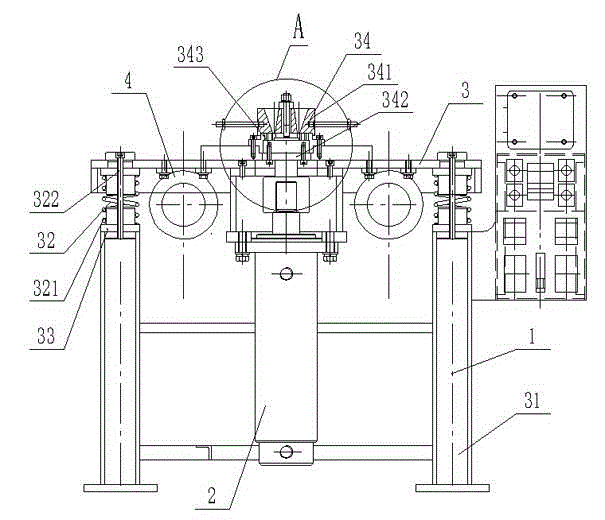
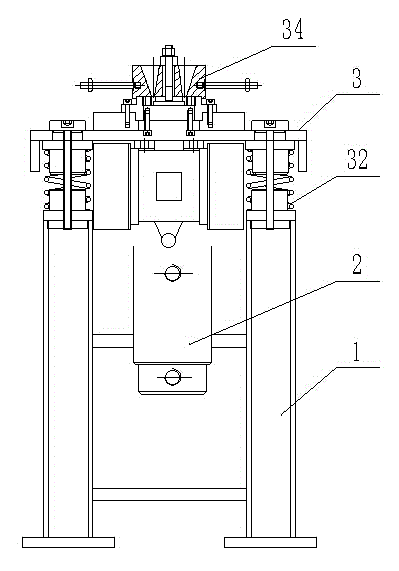
[0027] Such as Figure 1~5 As shown, an automatic submersible motor copper end ring casting machine includes a bracket 1 and an oil cylinder 2. The bracket 1 includes a plurality of supporting legs 31 and a workbench 3 arranged at the upper end of the plurality of legs 31. The workbench 3 and multiple legs 31 are connected by elastic devices 32, the workbench 3 can move up and down relative to the legs 31, the workbench 3 is provided with a concave-convex mold 34, the concave mold 341 of the concave-convex mold 34 is movably connected by bolts On the workbench 3, the cylinder body of the oil cylinder 2 is fixedly arranged on the support 1, the pist...


PUM


Abstract

The invention belongs to the technical field of manufacturing equipment of a copper end ring and particularly relates to special metal type automatic casting equipment of a submersible motor copper end ring. Aiming at solving the technical problems, an automatic submersible motor copper end ring casting machine with high manufacturing precision and good quality is provided. The technical scheme for solving the technical problems is as follows: the automatic submersible motor copper end ring casting machine comprises a bracket and an oil cylinder; the bracket comprises a plurality of supporting legs with supporting effects and a worktable arranged at the upper ends of the plurality of supporting legs; the worktable is connected with the plurality of supporting legs by elastic devices; a concave-convex die is arranged on the worktable; a concave die of the concave-convex die is movably connected with the worktable by a bolt; a cylinder body of the oil cylinder is fixedly arranged on the bracket; a piston rod of the oil cylinder is connected with the bottom end of a convex die; and a plurality of ejection columns for ejecting a casting piece are arranged at the upper end of the convex die. The casting piece produced by the automatic submersible motor copper end ring casting machine has good quality, good shrink filling performance, few pores, high precision and high density.

Description

Technical field [0001] The invention belongs to the technical field of manufacturing equipment for copper end rings, and in particular relates to a special metal type automatic casting equipment for copper end rings of submersible motors. Background technique [0002] The copper end ring of the submersible motor is an electrolytic copper structural part with 20 grain-shaped grooves and high precision. The manufacturing process is difficult. The traditional casting cannot meet the accuracy requirements. The mechanical processing is not only difficult but also costly. The shape of the powder metallurgy part And accuracy can be achieved, but the density is only about 7.6, which does not meet the electromagnetic requirements of the motor squirrel cage, and the melting point is low, the welding performance is poor, and it is eventually eliminated. Previously, some of the copper end rings of manufacturers in the submersible electric pump industry used the "blocking" process, some used ...

Claims


Application Information

Patent Timeline
Patent Type & Authority Applications(China)
IPC IPC(8): B22C9/08B22C9/24B22D27/08
CPCB22C9/06B22C9/082B22C9/24B22D27/08
Inventor 许正义
Owner SHANXI TIANHAI PUMP IND CO LTD
Why Eureka
Try Eureka