
Fixed fluidized bed reactor and using method thereof

A fixed fluidized bed and reactor technology, applied in the direction of chemical instruments and methods, chemical/physical processes, etc., can solve problems such as inapplicability, achieve the effects of inhibiting coking and carburizing, reducing impact, and avoiding negative effects

Active Publication Date: 2015-04-29
CHINA PETROLEUM & CHEM CORP +1
View PDF18 Cites 12 Cited by
  • Summary
  • Abstract
  • Description
  • Claims
  • Application Information

AI Technical Summary

Problems solved by technology

[0009] To sum up, the existing technology is mainly aimed at coking and carburizing in the large-scale production or medium-scale test of ethylene cracking and catalytic cracking of heavy oil, and is not suitable for laboratory small-scale fixed fluidized bed reactors.

Method used


Image

  • Fixed fluidized bed reactor and using method thereof
  • Fixed fluidized bed reactor and using method thereof
  • Fixed fluidized bed reactor and using method thereof

Examples


Embodiment 1

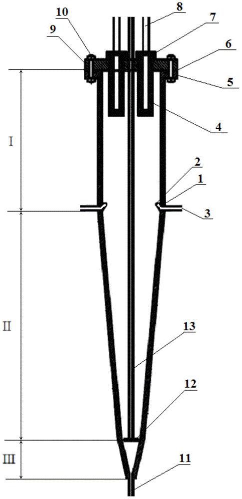
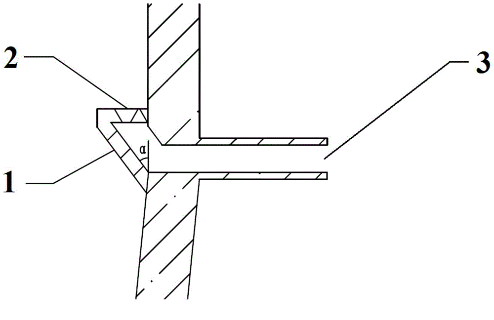
[0077] In the fixed fluidized bed reactor, the relevant dimensions of the coking inhibitor injection part at the bottom of the settling section I include: the angle α between the truncated cone baffle 1 and the wall of the settling section is 35°; the height of the truncated cone baffle It is 7% of the total height of the settling section; the ratio of the inner diameter to the outer diameter of the annular filter plate 2 is 0.8; the number of coking inhibitor injection ports is 2; the material of the annular filter plate is 00Cr17Ni14Mo2.

[0078] The carrier gas is steam, and the coking inhibitor is composed of carbon disulfide, ethanedithiol and dimethyl sulfide, and the mass ratio is 2:1:1; 1) The weight ratio is 2×10 -3 , the weight ratio of coking inhibitor to carrier gas is 3×10 -6 Catalyst adopts catalytic cracking catalyst, trade mark is CEP-1, and the character of catalyst is as shown in table 2, and operating conditions is as shown in table 3.

[0079] After the s...

Embodiment 2

[0081] In the fixed fluidized bed reactor, the relevant dimensions of the coking inhibitor injection part at the bottom of the settling section I include: the angle α between the truncated cone baffle 1 and the wall of the settling section is 35°; the height of the truncated cone baffle It is 15% of the total height of the settling section; the ratio of the inner diameter to the outer diameter of the annular filter plate 2 is 0.7; the number of coking inhibitor injection ports is 4; the material of the annular filter plate is 00Cr17Ni14Mo2.

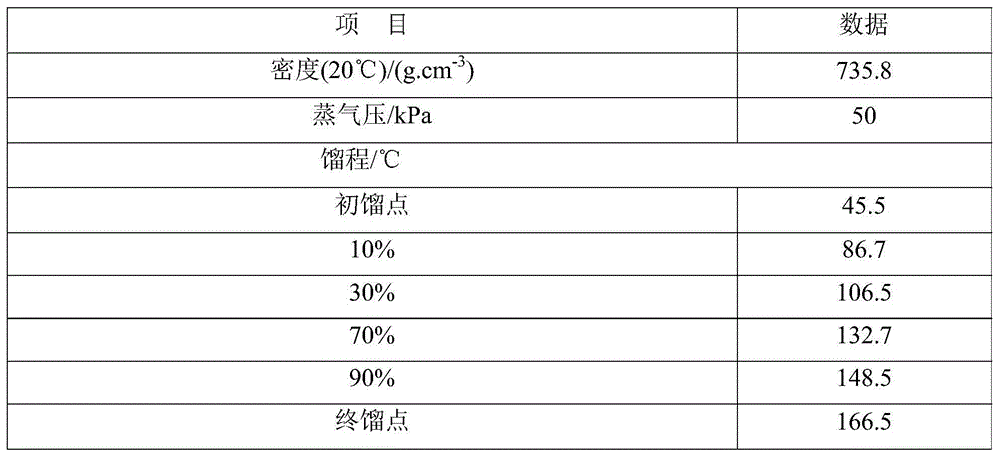
[0082] With water vapor as the carrier gas, the coking inhibitor is composed of carbon disulfide, ethanedithiol and dimethyl sulfide in a mass ratio of 2:1:1; The weight ratio of coking inhibitor injection amount to hydrocarbon feedstock (straight-run naphtha, see Table 1 for properties) is 4×10 -3 ; The weight ratio of coking inhibitor to carrier gas is 3×10 -6 Catalyst adopts catalytic cracking catalyst, trade mark is CEP-1, and the ch...


PUM


Abstract

The invention discloses a fixed fluidized bed reactor and a using method thereof. The fixed fluidized bed reactor comprises a top sealing structure and a reactor main body, as well as an outlet pipe and a feeding pipe which are communicated with the reactor main body, wherein the reactor main body comprises a settling section, a reaction section and an oiling agent initial contact section from top to bottom, wherein a coking inhibitor injecting part is arranged at the bottom of the settling section, the coking inhibitor injecting part comprises a frustum-shaped baffle plate arranged in the circumferential direction of the inner wall of the bottom of the settling section, an annular filter plate for connecting the top of the frustum-shaped baffle plate with the inner wall of the reactor main body, and a coking inhibitor injecting hole, a cavity is formed among the frustum-shaped baffle plate, the annular filter plate and the inner wall of the reactor main body, and the coking inhibitor injecting hole is communicated with the cavity. By adopting the fixed fluidized bed reactor disclosed by the invention, a coking inhibitor is injected through the coking inhibitor injecting part, so that the yield of coke can be remarkably reduced.

Description

technical field [0001] The invention relates to a fixed fluidized bed reactor and a method for using the fixed fluidized bed reactor. Background technique [0002] Due to the advantages of wide sources of raw materials, easy adjustment of olefin product structure, low energy consumption and less carbon dioxide emissions, catalytic cracking technology has achieved rapid development in recent years. The process development and catalyst development around this technical field, or the screening and evaluation of different feedstock oils and catalysts, are inseparable from small laboratory evaluation devices. At present, the fixed fluidized bed device is widely used in catalytic cracking experiments due to its advantages of simple structure, good operating flexibility, bed isothermal, and high heat transfer efficiency. [0003] The fixed fluidized bed reactor is the core equipment of the small fixed fluidized bed in the laboratory. It is the component with the highest temperatur...

Claims


Application Information

Patent Timeline
Patent Type & Authority Applications(China)
IPC IPC(8): B01J8/24
CPCB01J8/24
Inventor 任世宏毛安国魏晓丽
Owner CHINA PETROLEUM & CHEM CORP
Learn More