Pin positioning device and pin positioning whole device including same

A technology for positioning devices and pins, which is applied in the fields of overall pin positioning devices, positioning devices, and pin positioning devices. The effect of improving and improving quality

Active Publication Date: 2015-04-22
SUZHOU ACCURACY ASSEMBLY AUTOMATION CO LTD
View PDF3 Cites 0 Cited by
  • Summary
  • Abstract
  • Description
  • Claims
  • Application Information

AI Technical Summary

Problems solved by technology

In the traditional packaging, the positioning of the pins is mainly fixed by hand, but because the hands are often stained with some acidic or other substances, if they touch the pins, they will be corroded and polluted the pins , and once the pins are corroded, it will affect the performance of the sensor, so even if it is done manually, the staff can only use tweezers and other tools, and rely on equipment such as wire threading machines to complete the positioning of the pins, and then proceed Dispensing and other packaging processes
[0004] However, the above-mentioned various sensors have different sizes due to their volume, so their pins are also thin and thick. Manual operation can also easily locate it for some thicker pins, but for some pins that are thinner than a hair The positioning of the pins is still thin, and the positioning effect of manual operation may not be satisfactory.
[0005] At the same time, because manual operation is difficult to unify each operation of each person, the randomness of its operation will lead to inconsistent positioning effects for different pins or different batches of pins, affecting the quality of subsequent dispensing and It will be different, for example, there is a deviation in the positioning position between the various pins, and the dispensing position of the dispensing head is indeed uniform, which will cause uneven dispensing of some sensors, so it is reliable; and manual operation The efficiency is not high, even for some skilled workers, their daily workload is very limited, it is difficult to guarantee a high work efficiency

Method used


Image

  • Pin positioning device and pin positioning whole device including same
  • Pin positioning device and pin positioning whole device including same
  • Pin positioning device and pin positioning whole device including same

Examples


Embodiment Construction

[0037] Preferred embodiments of the present invention will be described in detail below in conjunction with the accompanying drawings.

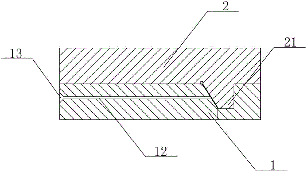
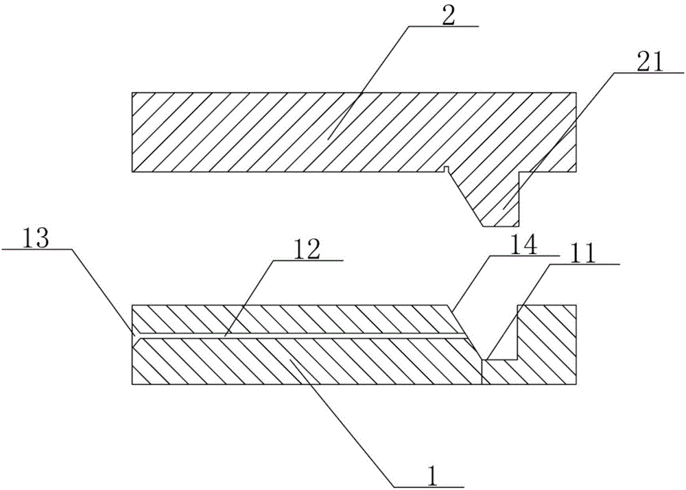
[0038] In order to achieve the purpose of the present invention, as Figure 1-2 As shown, in one embodiment of the pin positioning device of the present invention, it mainly includes a first positioning element 1 and a second positioning element 2, wherein a groove 11 is opened on the first positioning element 1, and the concave The groove 11 is opened from the top of the first positioning element 1 towards the bottom in the figure, and the groove 11 can be set as a large groove, or can be set as a plurality of side-by-side grooves, and the first positioning element 1 also has A through hole 12 is also provided along its length direction, and the through hole 12 extends from one end of the first positioning element 1 into the groove 11, that is, opens between one end of the first positioning element 1 and the groove 11 A channel, if the widt...


PUM


Abstract

The invention discloses a pin positioning device which comprises first positioning elements and second positioning elements. At least one groove is formed in each fist positioning element, and at least one through hole is formed in each first positioning element in the length direction. The through holes extend from one ends of the first positioning elements to the grooves. The second positioning elements are provided with bumps matched with the grooves, and the bumps are arranged in the grooves. In addition, the invention further discloses a pin positioning whole device including the pin positioning device. Compared with the prior art, the original manually positioning operations are totally replaced; on one hand, potential pollution and corrosion on pins caused by manual operations are avoided, on the other hand, tools and equipment such as tweezers and a threading machine are not needed. Threading the pins into the through holes is only needed. Accordingly, the work efficiency is improved; meanwhile, the positioning of multiple pins is unified, and the packaging quality is improved.

Description

technical field [0001] The invention relates to a positioning device in the field of semiconductor packaging, in particular to a pin positioning device and an overall pin positioning device including the pin positioning device. Background technique [0002] For the packaging of sensors such as thermistors, diodes, and silicon semiconductors, the first thing to do is to locate the pins of the sensors, and then perform packaging processes such as dispensing. [0003] Among them, the positioning of the pins has become an important factor in the effect of packaging processes such as dispensing. In the traditional packaging, the positioning of the pins is mainly fixed by hand, but because the hands are often stained with some acidic or other substances, if they touch the pins, they will be corroded and polluted the pins , and once the pins are corroded, it will affect the performance of the sensor, so even if it is done manually, the staff can only use tweezers and other tools, ...

Claims


Application Information

Patent Timeline
Patent Type & Authority Applications(China)
IPC IPC(8): H01L21/68
CPCH01L21/68
Inventor 苏洁
Owner SUZHOU ACCURACY ASSEMBLY AUTOMATION CO LTD
Why Eureka
Try Eureka