
Clamping device for transformer coil and work method of clamping device

A clamping device and inner ring technology, applied in the manufacture of inductors/transformers/magnets, coils, electrical components, etc., can solve problems such as difficulty in meeting requirements, low work efficiency, and poor forming effects, and achieve good forming effects and work high efficiency effect

Inactive Publication Date: 2015-04-22
WUHU JINNIU ELECTRIC
View PDF6 Cites 1 Cited by
  • Summary
  • Abstract
  • Description
  • Claims
  • Application Information

AI Technical Summary

Problems solved by technology

[0004] 1. The forming effect is poor, even if it is corrected, it is difficult to meet the requirements;
[0005] 2. Low work efficiency, manual correction is difficult to improve efficiency

Method used


Image

  • Clamping device for transformer coil and work method of clamping device
  • Clamping device for transformer coil and work method of clamping device
  • Clamping device for transformer coil and work method of clamping device

Examples


Embodiment

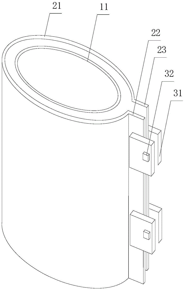
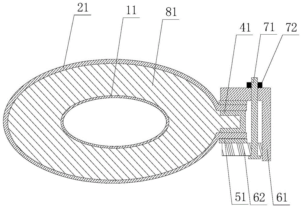
[0040] Figure 1-2 The basic structural diagram of the clamping device of the transformer coil in Embodiment 1 of the present invention is schematically given, as Figure 1-2 As shown, the clamping device includes:

[0041] A cylindrical inner ring 11 and a cylindrical outer ring 21. In the vertical direction, the inner ring and the outer ring are formed with arc surfaces and have openings. The openings include extensions 22 and 23 on both sides;

[0042] A support piece 81, the support piece is in the shape of a standard coil, and is installed horizontally between the inner ring and the outer ring;

[0043] Spacer 41, the spacer is between the extensions forming the two sides of the opening; the horizontal section of the spacer is in the shape of “[”, and supports are provided in the horizontal direction inside to improve strength, such as welding metal strip.

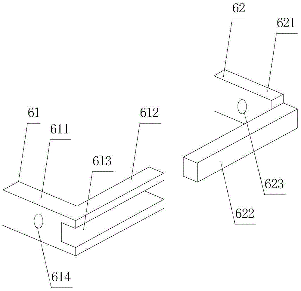
[0044] The pressing block 51, which is a strip of metal, is arranged on the outside of the extensions 22, 23 whe...


PUM


Abstract

The invention provides a clamping device for a transformer coil and a work method of the clamping device. The clamping device comprises a cylindrical inner ring, a cylindrical outer ring, a supporting sheet, a cushion block, a locating piece set and locating pieces, wherein in the vertical direction, a curved face is formed by the inner ring and the outer ring, and an opening is formed and comprises extending parts on the two sides; the supporting sheet is of a standard coil shape and horizontally installed between the inner ring and the outer ring; the cushion block is located between the extending parts located on the two sides and forming the opening; locating pieces of the locating piece set are arranged outside the extending parts on the two sides in a relatively-moving mode and the locating pieces are connected with and fixed to the locating piece set. The clamping device has the advantages of being good in forming effect, high in work efficiency and the like.

Description

technical field [0001] The invention relates to a clamping device, in particular to a clamping device for a transformer coil and a working method thereof. Background technique [0002] Power transformers are one of the main equipment in power plants and substations. The role of the transformer is multifaceted. It can not only increase the voltage to send electric energy to the power consumption area, but also reduce the voltage to the voltage used at all levels to meet the needs of power consumption. [0003] A power transformer includes an iron core and its outer low-voltage coils and high-voltage coils. Due to human factors in the winding process, the inner and outer sides of the wound coil are not standard arcs or planes, which need to be corrected to improve work performance. The usual practice is to use a hammer to hit the outer coils to make them meet the requirements. This method has disadvantages: [0004] 1. The forming effect is poor, even if it is corrected, i...

Claims


Application Information

Patent Timeline
Patent Type & Authority Applications(China)
IPC IPC(8): H01F41/06H01F41/04H01F41/077
Inventor 刘朝振陈明珠崔伟林
Owner WUHU JINNIU ELECTRIC
Learn More