Bar code reading device
A bar code reading and bar code technology, applied in the field of bar code reading optical engine, can solve the problem that the speed of reading bar code is not fast enough, and achieve the effect of fast decoding speed, enhancing field of view, and improving decoding rate
- Summary
- Abstract
- Description
- Claims
- Application Information
AI Technical Summary
Problems solved by technology
Method used
Image
Examples
Embodiment 1
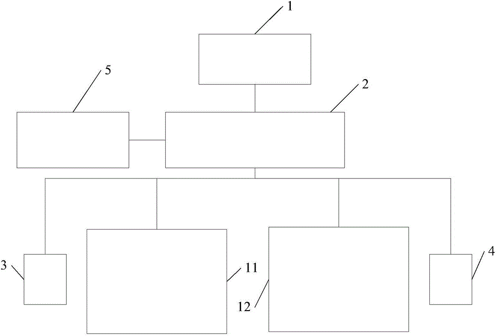
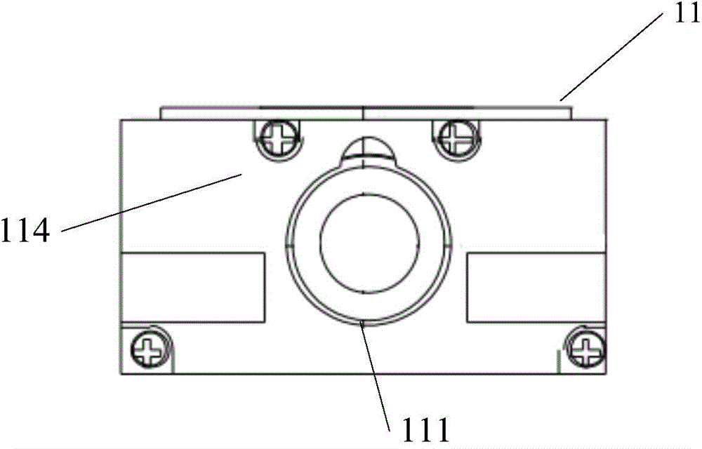
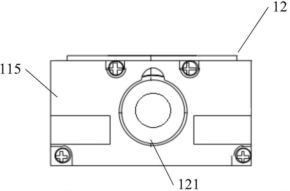
[0097] Such as Figure 1-6 Shown is a preferred embodiment of a barcode reading device of the present invention. The barcode reading device includes: a decoding trigger module 1; a control coordination module 2; at least two barcode decoding engines; at least one aiming light source 3; at least one illuminating light source 4;
[0098] in:
[0099] The decoding trigger module 1 sends an instruction to read the barcode to the control coordination module. Such as Image 6 As shown, the decoding trigger module 1 can be triggered by a key. The decoding trigger module can also be triggered by sensor sensing.
[0100] The control coordination module 2, for example, can adopt chips such as STM32 of STMicroelectronics, and after receiving the reading barcode instruction, send work instructions to at least two barcode decoding engines according to the order of setting, and control the lighting source and aiming light source to start, receive The barcode decoding data sent by the b...
Embodiment 2
[0121] Such as Figure 9 As shown, on the basis of the above-mentioned embodiment 1, the first decoding chip 113 is the same as the second decoding chip 123, and the decoding chip further includes:
[0122] The scanning module 21 generates scanning coordinates corresponding to address bits in an address storage space of an external data memory (not shown). The scanning module 21 scans the barcode image;
[0123] The boundary identification module 22 reads the barcode image according to the scanning coordinates, and calculates the read image pixel points to obtain the bar-space boundary points of the barcode image;
[0124] The direction identification module 23 calculates and obtains the direction of the barcode according to the boundary point of the bar code acquired by the boundary identification module;
[0125] The bar-space boundary processing module 24 processes the barcode image according to the barcode direction, so as to obtain the bar-space boundary in the barcode ...
Embodiment 3
[0136] On the basis of Embodiment 1, the decoding chip is different from the second decoding chip, and the first decoding chip, such as Figure 9 As shown, further includes:
[0137] The scanning module 21 generates scanning coordinates corresponding to address bits in an address storage space of an external data memory (not shown). The scanning module 21 scans the barcode image;
[0138] The boundary identification module 22 reads the barcode image according to the scanning coordinates, and calculates the read image pixel points to obtain the bar-space boundary points of the barcode image;
[0139] The direction identification module 23 calculates and obtains the direction of the barcode according to the boundary point of the bar code acquired by the boundary identification module;
[0140] The bar-space boundary processing module 24 processes the barcode image according to the barcode direction, so as to obtain the bar-space boundary in the barcode image;
[0141] The sym...
PUM
 Abstract
Description
Claims
Application Information
 - R&D
- Intellectual Property
- Life Sciences
- Materials
- Tech Scout
- Unparalleled Data Quality
- Higher Quality Content
- 60% Fewer Hallucinations
Browse by: Latest US Patents, China's latest patents, Technical Efficacy Thesaurus, Application Domain, Technology Topic, Popular Technical Reports.
© 2025 PatSnap. All rights reserved.Legal|Privacy policy|Modern Slavery Act Transparency Statement|Sitemap|About US| Contact US: help@patsnap.com


