
Shallow sea multi-path sound signal decomposition method

A technology of signal decomposition and multi-channel sound, which is applied in the direction of sound wave re-radiation, re-radiation utilization, and measurement devices, can solve the problems of inability to reflect the frequency and phase characteristics of sub-channels, achieve improved decomposability, simplified operating procedures, Strong operability effect

Active Publication Date: 2015-04-22
HARBIN ENG UNIV
View PDF3 Cites 6 Cited by
  • Summary
  • Abstract
  • Description
  • Claims
  • Application Information

AI Technical Summary

Problems solved by technology

This method simplifies the effect of sound rays on sound waves, and cannot reflect the frequency and phase characteristics of each sub-channel, which has great limitations
In shallow seas, what impact each multi-channel sub-channel has on the transmitted signal, and how to separate each multi-channel sub-signal, at present, there are few reports at home and abroad that discuss this direction in depth

Method used


Image

  • Shallow sea multi-path sound signal decomposition method
  • Shallow sea multi-path sound signal decomposition method
  • Shallow sea multi-path sound signal decomposition method

Examples


Embodiment Construction

[0029] The following will combine figure 1 ~ Fig. 8 illustrates the present invention in further detail.

[0030] Shallow sea multi-channel sound signal decomposition method of the present invention is divided into the following steps:

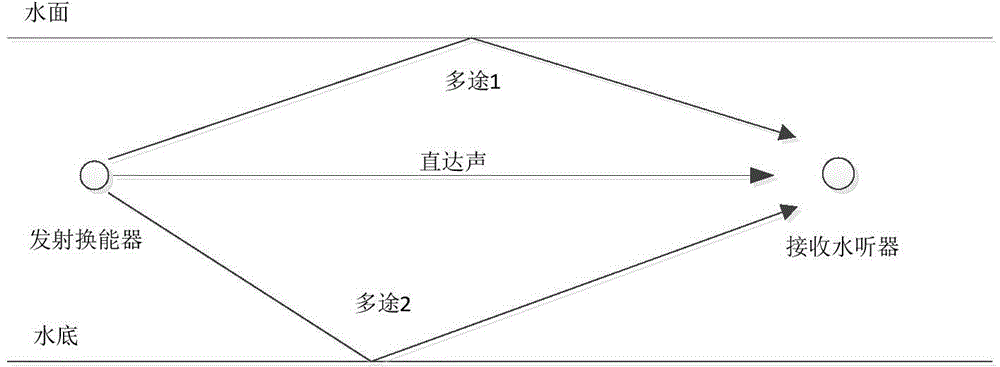
[0031] (1) The distribution of sonar transmitters and receivers is as follows: figure 2 shown;

[0032] (2) Use the electrical signal x(t) to drive the sonar emission device, as shown in Figure 4(a);

[0033] (3) The sound pressure signal received by the sonar receiving device is y(t), as shown in Figure 4(b);

[0034] (4) Do a fractional Fourier transform on the signal y(t), and take the optimal order (let α=α at this time 0 ) output, the output is the curve of time-frequency domain u and amplitude, such as Figure 5 shown;

[0035] (5) extraction Figure 5 The value u of the 7 main peaks in the u domain i (i=0,1,…,6), and use formula (2) to convert to delay parameter τ i (i=0,1,...,6);

[0036] τ i...


PUM


Abstract

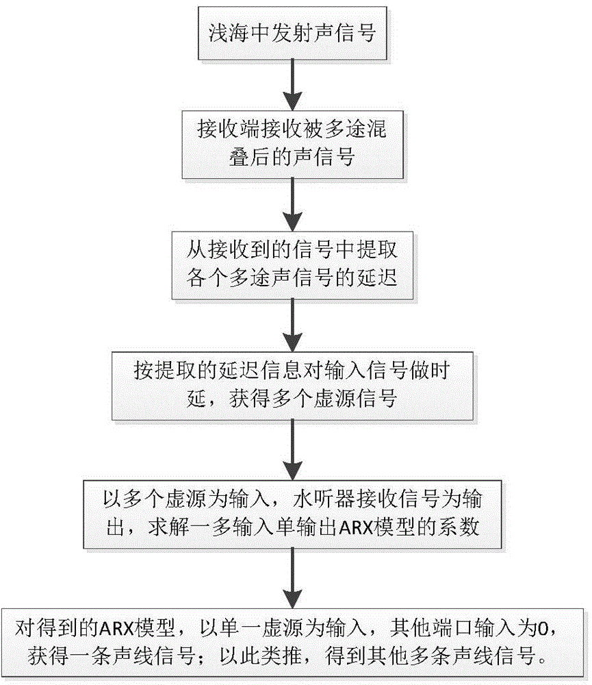
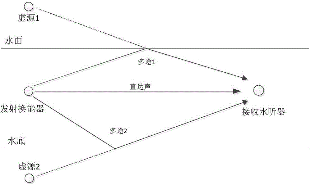
The invention discloses a shallow sea multi-path sound signal decomposition method. The shallow sea multi-path sound signal decomposition method includes the following steps that a sonar emitting device emits signals, and a sonar receiving device receives signals; the delay of each multi-path sound signal is extracted from the received signals; the emitted signals are delayed according to the extracted delay, and an actual source signal and N-1 virtual source signals are obtained; the obtained actual source signal and N-1 virtual source signals serve as input, the received signals serve as output, and an ARX model is constructed; the kth virtual source signal serves as input and fed into the ARX model, the other k-1 virtual source signals are set as 0, and a sound signal is obtained; it is made that k=k+1, the former step is repeated until k=N, and N sound signals are obtained. The shallow sea multi-path sound signal decomposition method effectively improves the decomposability of the multi-path signals.

Description

technical field [0001] The invention belongs to the field of signal processing, and in particular relates to a method for decomposing multi-channel sound signals in shallow seas, which can obtain various multi-channel sub-signals. Background technique [0002] Most of China's sea areas are shallow seas, and many hydroacoustic equipment work in shallow seas. A key factor affecting sound propagation and reception in shallow seas is multi-path interference, which causes intersymbol interference in underwater acoustic communication systems and affects communication rates; in target echo testing, the incident waves of the target are aliased in time and space, There is no way to get the target's response in a fixed direction. Multi-channel signal separation can reduce reception interference and improve the performance of equipment in shallow seas. The study of multi-channel signal separation in shallow sea has important theoretical significance and practical value. [0003] The...

Claims


Application Information

Patent Timeline
Patent Type & Authority Applications(China)
IPC IPC(8): G01S7/527G01S7/536G01S15/02
CPCG01S7/527G01S7/536G01S15/02
Inventor 赵安邦何呈惠娟牛芳宋雪晶祝令国程越曾才高毕雪洁马琳
Owner HARBIN ENG UNIV
Learn More