
Target detection method by use of airborne early warning radar

An airborne early warning and detection method technology, which is applied in the field of airborne early warning radar target detection and airborne early warning radar signal processing, can solve the problems of large amount of calculation, difficulty in ensuring real-time performance, and unfavorable detection of low-speed small targets

Inactive Publication Date: 2015-04-22
XIDIAN UNIV
View PDF5 Cites 9 Cited by
  • Summary
  • Abstract
  • Description
  • Claims
  • Application Information

AI Technical Summary

Problems solved by technology

In practical applications, STAP technology mainly has the following two problems: First, in a non-uniform clutter environment, it is necessary to obtain enough independent and identically distributed (IID) training samples for estimating the covariance matrix It is very difficult; secondly, even if the requirements of the training samples are met, the problem of excessive calculation in all-time processing will make it difficult to guarantee real-time performance
However, the main disadvantage of this method is that the number of overcomplete bases for sparsely representing the clutter spectrum is undetermined, but it is much larger than the system degrees of freedom. In practice, the system degrees of freedom are usually tens of thousands, so that in each distance unit sample The amount of calculation required in the process of reconstruction of the covariance matrix is ​​very large, which is not conducive to real-time processing, thus affecting its actual engineering application effect
However, this method still has the disadvantage that the notch width of the filter designed to suppress the clutter is artificially set, and cannot adaptively perceive the clutter ridges in the actual data. The minimum detectable speed becomes larger, which is very unfavorable for the detection of low-speed small targets

Method used


Image

  • Target detection method by use of airborne early warning radar
  • Target detection method by use of airborne early warning radar
  • Target detection method by use of airborne early warning radar

Examples


Embodiment Construction

[0053] The present invention will be further described below in conjunction with accompanying drawing:

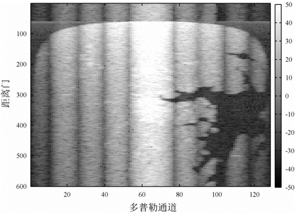
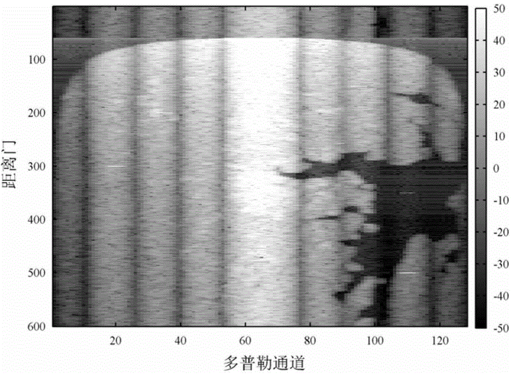
[0054] refer to figure 1 , is a flow chart of an airborne early warning radar target detection method of the present invention, the present invention is used for airborne early warning radar signal processing, and its specific implementation steps are as follows:

[0055] Step 1, using the airborne early warning radar antenna to receive space-time two-dimensional echo data.

[0056] Step 1 specifically includes the following sub-steps:

[0057] 1a) Set the airborne early warning radar to work in front and side view mode.

[0058] 1b) Use the airborne early warning radar to transmit signals; the receiving array of the airborne early warning radar is a uniform linear array composed of N array elements, and use the receiving array of the airborne early warning radar to receive the ground signal within the coherent accumulation time of M pulses. The space-time two-dimensiona...


PUM


Abstract

The invention belongs to the technical field of radar clutter inhibition and in particular relates to a target detection method by use of airborne early warning radar. The target detection method comprises the following specific steps: receiving space-time two-dimensional echo data by use of airborne early warning radar; determining normalized space-time two-dimensional frequency points corresponding to the positions of a clutter ridge curve related to the space-time two-dimensional echo data; constructing a clutter ridge steering vector basis matrix Psi according to the normalized space-time two-dimensional frequency points corresponding to the positions of the clutter ridge curve; constructing a matrix element error vector Es and a new clutter ridge steering vector basis matrix Psi', and performing iterative fitting on the data of the first unit to be tested in distance under the least square constraint by use of the new clutter ridge steering vector basis matrix Psi', thereby obtaining the fitted residual data of the first unit to be tested in distance; performing unit average constant false alarm rate detection on the fitted residual data of the first unit to be tested in distance, thereby obtaining a target detection result.

Description

technical field [0001] The invention belongs to the technical field of radar clutter suppression, in particular to an airborne early warning radar target detection method, which can be used for airborne early warning radar signal processing. Background technique [0002] The main task of airborne early warning radar is to detect targets in complex clutter background and to locate and track them. Effective suppression of clutter is the core means to improve the performance of early warning radar. Space-time adaptive processing (STAP) technology makes full use of airspace and time domain information, while coherently accumulating target signals, and filters ground clutter through space-time adaptive processing to realize airborne radar detection. efficient detection of targets. For example, the E2-D airborne early warning radar of the United States adopts this technology. In practical applications, STAP technology mainly has the following two problems: First, in a non-unifor...

Claims


Application Information

Patent Timeline
IPC IPC(8): G01S7/36
CPCG01S7/36G01S7/41
Inventor 王彤任鹏丽同亚龙吴建新
Owner XIDIAN UNIV
Learn More