
Powder drying device

A drying device and powder technology, applied in drying, drying machine, heating device and other directions, can solve the problems of high cost input, large plane space occupation, and many equipments, etc.

Inactive Publication Date: 2015-04-22
CHANGZHOU HUAHAO KNITTING
View PDF0 Cites 2 Cited by
  • Summary
  • Abstract
  • Description
  • Claims
  • Application Information

AI Technical Summary

Problems solved by technology

[0002] The existing powder drying device includes an oven, and a heater is arranged in the oven, and then the powder is transported in the oven through a conveying mechanism passing through the oven, so as to realize the drying of the powder. Such a structure usually adopts a horizontal type, Occupies a large plane space, uses a lot of equipment, and costs a lot, and because the powder is transported by a conveying mechanism, the powder cannot be turned over, resulting in poor drying effect

Method used


Image

  • Powder drying device

Examples


Embodiment Construction

[0009] The present invention will be further described below in conjunction with the accompanying drawings and specific embodiments.

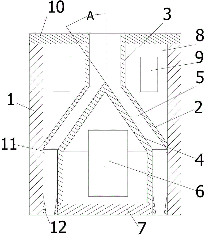
[0010] Such as figure 1 , a powder drying device, comprising an oven 1, a material guide cylinder 3 with a bell mouth 2 in the oven, and a conical heating device below the material guide cylinder, the conical heating device includes a conical shell 4, the conical shell The tapered end of the tapered end is adapted to the bell mouth of the material guide cylinder, and a tapered drying channel 5 is formed between the outer surface of the tapered end of the conical shell and the inner surface of the material guide tube bell mouth, and the tapered A heater 6 for heating the conical shell is provided in the shell. The lower end of the conical shell 4 is sealed with a base 7 to ensure the sealing performance of the conical shell and enhance the heat preservation effect; The angle A between the outer surface of the conical end of the shell and the c...


PUM


Abstract

The invention relates to the technical field of biochemical drying equipment, and specifically relates to a power drying device. The device comprises a drying oven; a guide barrel equipped with a loudspeaker-shaped opening and a tapered heating device positioned below the guide barrel are arranged in the drying oven; the tapered heating device comprises a tapered housing; the tapered end of the tapered housing is adapted to the loudspeaker-shaped opening of the guide barrel; a tapered drying channel is formed between the outer surface of the tapered end of the tapered housing and the inner surface of the loudspeaker-shaped opening of the guide barrel; a heater for heating the tapered housing is arranged in the tapered housing. According the powder drying device, the guide barrel is equipped with the downward loudspeaker-shaped opening through which powder can flow through the guide barrel and the drying channel and be directly discharged from the drying oven under the weight effect without the conveying mechanisms in the prior art, and therefore, the cost of devices can be decreased; in addition, the powder can be overturned during lowering down under the weight effect, and thus the drying efficiency can be increased.

Description

technical field [0001] The invention relates to the technical field of chemical drying equipment, in particular to a powder drying device. Background technique [0002] The existing powder drying device includes an oven, and a heater is arranged in the oven, and then the powder is transported in the oven through a conveying mechanism passing through the oven, so as to realize the drying of the powder. Such a structure usually adopts a horizontal type, Occupies a large plane space, uses a lot of equipment, and has high cost input, and because the powder is transported by a conveying mechanism, the powder cannot be turned over, resulting in poor drying effect. Contents of the invention [0003] In view of the above-mentioned problems, the present invention provides a powder drying device with reasonable structural design, small plane occupation space, reversible powder and good drying effect. [0004] The present invention is realized through the following technical solutio...

Claims


Application Information

Patent Timeline
IPC IPC(8): F26B3/04F26B17/12F26B23/10F26B23/00
Inventor 李才君
Owner CHANGZHOU HUAHAO KNITTING
Learn More