thrust vectoring nozzle

A thrust vectoring and nozzle technology, which is applied in the field of aircraft, can solve the problem that the working life of the ternary vector tail nozzle cannot meet the service requirements and other problems.

Active Publication Date: 2017-03-01
蚌埠中知知识产权运营有限公司
View PDF4 Cites 0 Cited by
  • Summary
  • Abstract
  • Description
  • Claims
  • Application Information

AI Technical Summary

Problems solved by technology

Although the existing vectoring nozzle can improve the air maneuverability of fighter jets, the disadvantage is that the tail nozzle can only reach the level of binary vector (ie, up and down deflection)
Or the working life of the ternary vector tail nozzle is not as long as the service requirement

Method used


Image

  • thrust vectoring nozzle
  • thrust vectoring nozzle

Examples


Embodiment Construction

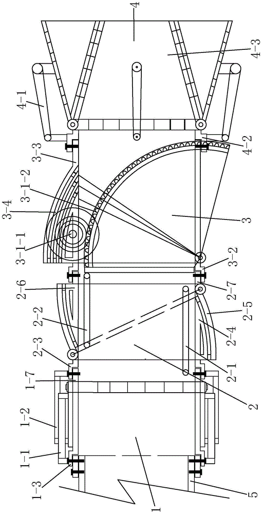
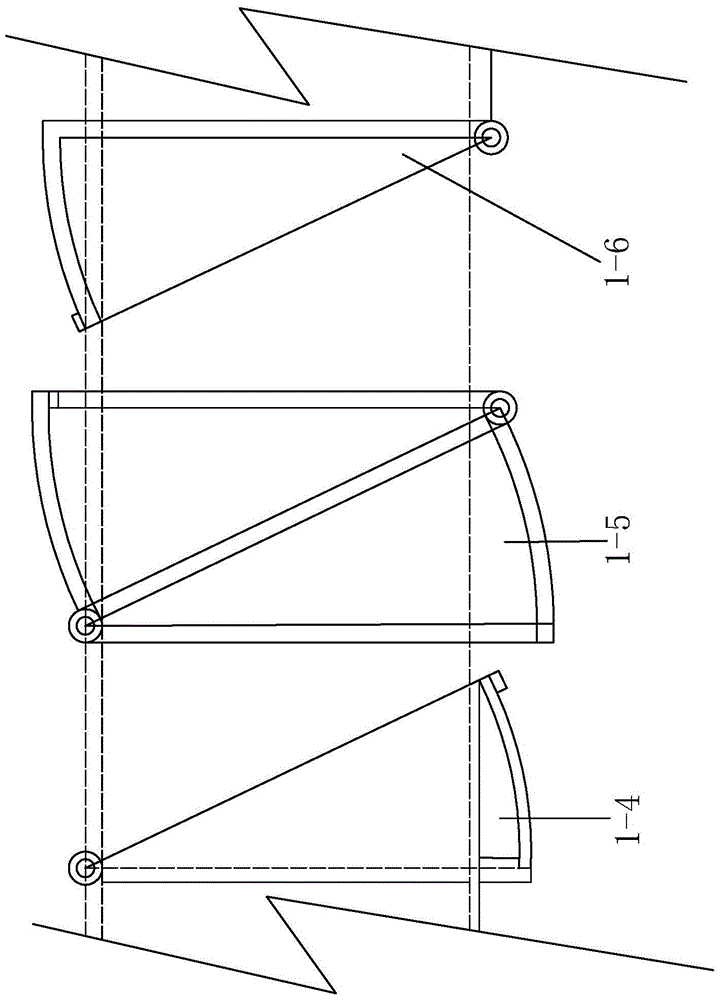
[0049] A thrust vectoring nozzle such as figure 1 As shown, it is mainly composed of 4 functional components, and these 4 functional groups start from the tail of the aircraft and are connected in series from front to back. The above four components are all made and socketed on the basis of square sleeves made of thin-walled plates, and they are in turn: the first functional component 1, that is, the left and right deflection functional sleeves and their hydraulic cylinders, which The function is to make the nozzle deflect left and right on the horizontal plane. The second functional component 2, that is, the vertical deflection functional casing and its hydraulic cylinder, has the function of making the nozzle deflect up and down. The third functional component 3, that is, the vertical downward deflection function casing and its hydraulic motor 3-1-1 actuating rack 3-1-2 assembly, its function is to make the nozzle vertically deflect downward and realize the nozzle The anti...


PUM


Abstract

The invention discloses a thrust vector nozzle. The thrust vector nozzle is formed by serial connection of two function assemblies, wherein the two function assemblies are of the same structure and are arranged in a manner of 90-degree shaft staggered rotation in the flying direction. The two function assemblies include a first function assembly achieving the left and right deflection function and a second function assembly achieving the up and down deflection function. The front portion of the first function assembly is communicated with an engine exhaust pipe of an aircraft, and the front portion of the second function assembly is communicated with the rear portion of the first function assembly; or the front portion of the second function assembly is communicated with the engine exhaust pipe of the aircraft, and the front portion of the first function assembly is communicated with the rear portion of the second function assembly. The thrust vector nozzle has the advantages of being simple in structure, high in durability strength, good in structural part interchangeability, rapid and flexible in operation and reaction and good in invisibility.

Description

technical field [0001] The invention relates to the technical field of aircraft, in particular to a thrust vectoring nozzle installed at the tail of an aircraft. Background technique [0002] The aircraft relies on various aerodynamic rudder surfaces such as ailerons, elevators, and rudders to move in the air with 6 degrees of freedom. This aerodynamic rudder surface is very inefficient when the aircraft is at low speed, and its aerodynamic resistance is very large at high speed, such as supersonic flight. At the same time, the range of the angle of attack of the aircraft working in the airflow must be strictly controlled, otherwise it is very easy to stall, causing the aircraft to enter a spiral state and lose control. [0003] In order to avoid the above-mentioned problems, the thrust of the jet engine can be used to control the aircraft by changing the direction of the jet flow to control the aircraft. This is the technology of thrust vector control (TVC-Technical of Vic...

Claims


Application Information

Patent Timeline
Patent Type & Authority Patents(China)
IPC IPC(8): F02K1/10
Inventor 覃勇
Owner 蚌埠中知知识产权运营有限公司
Why Eureka
Try Eureka