A long screw pile machine

A technology of long auger pile driver and auger bit, which is applied to the driving device of rotary combined drilling, drilling equipment, earthwork drilling and production, etc., and can solve the problems of delay in construction period, waste of drill bits, and low work efficiency

Active Publication Date: 2017-12-22
WEIHAI HYDRAULIC & GEOTECHN ENG
View PDF8 Cites 0 Cited by
  • Summary
  • Abstract
  • Description
  • Claims
  • Application Information

AI Technical Summary

Problems solved by technology

[0002] At present, the main equipment for pile foundation construction is the long screw pile driver, which includes two parts: the hydraulic walking pile frame and the drilling system. , Control room, hydraulic system and electrical system. The drilling system includes a power head and a drilling tool. The output shaft of the power head and the auger bit are hollow. The auger bit is divided into single-head single-screw, double-head single-screw, and double-head double-screw. The advantages are simple operation, convenient use, The drilling efficiency is high, but when piling in complex areas, due to the influence of the torque of the power head, anti-seismic, anti-impact performance and the height of the pile body, the work efficiency is low, especially when encountering rock formations with high geological hardness, When there are large rocks or other hard substances, it is often impossible to continue to find. In serious cases, the drill bit may be damaged, and it is very troublesome to replace the drill bit. It is necessary to completely pull out the long screw rod of the pile driver to replace the drill bit. Not only is the drill bit wasted, but more importantly The most important thing is to delay the construction period and cause greater economic losses

Method used


Image

  • A long screw pile machine
  • A long screw pile machine
  • A long screw pile machine

Examples


Embodiment Construction

[0013] The present invention will be further described below in conjunction with the accompanying drawings. (The description below is as clear as possible, with data plus some data)

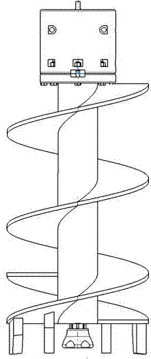
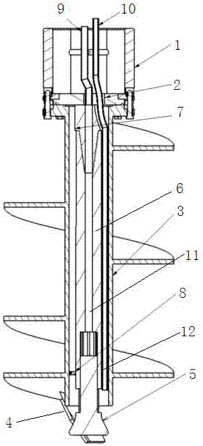
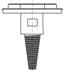
[0014] As shown in the figure, a long screw pile machine consists of two parts: a pile frame and a drilling system. System and electrical system, the input system includes the power head and the drilling tool, the screw drill rod (output shaft) of the power head is connected with the screw drill bit 1, the flange 2 and the auger bit 3, and the lower end surface of the auger bit 3 is provided with Drilling tool 4, the structure of above-mentioned each component and the interconnection relation between them are identical with prior art, this does not go into details, the feature of the present invention is that auger bit 3 is provided with central through hole, and in the central through hole of auger bit 3 There is a down-the-hole hammer 5 protruding from the drilling tool. The upper end of the d...


PUM


Abstract

The invention discloses a long screw pile machine. The machine is characterized in that a central through hole is formed in a screw bit, a down-hole hammer stretching out of a drill is arranged in the central through hole of the screw bit and is connected with a tapered threaded rod on a flange through a tapered threaded hole in the upper end of a handle to achieve location. A limit plate is arranged between the down-hole hammer handle and the screw bit through hole. An air through pipe and a water through pipe are arranged on the flange, an inlet of the air through pipe is communicated with an air guide pipe in a screw drill rod and a screw bit joint, an outlet of the air through pipe is communicated with an air inlet pipe in the down-hole hammer handle, an inlet of the water through pipe is communicated with a water guide pipe in the screw drill rod and the screw drill joint, an outlet of the water through pipe is connected with a water injection pipe, an outlet of the water injection pipe is formed in a lower port of the screw drill central through hole, and the air guide pipe and the water guide pipe in the screw drill rod and the screw drill joint are communicated with an air pipe and a water pipe on a power head. The machine has the advantages of being novel in structure, simple to operate, high in work efficiency, long in service life, wide in application range and the like.

Description

technical field [0001] The invention relates to pile foundation construction equipment, in particular to a long screw pile machine suitable for deep pile foundation construction in complicated areas. Background technique [0002] At present, the main equipment for pile foundation construction is the long screw pile driver, which includes two parts: the hydraulic walking pile frame and the drilling system. , Control room, hydraulic system and electrical system. The drilling system includes a power head and a drilling tool. The output shaft of the power head and the auger bit are hollow. The auger bit is divided into single-head single-screw, double-head single-screw, and double-head double-screw. The advantages are simple operation, convenient use, The drilling efficiency is high, but when piling in complex areas, due to the influence of the torque of the power head, anti-seismic, anti-impact performance and the height of the pile body, the work efficiency is low, especially...

Claims


Application Information

Patent Timeline
Patent Type & Authority Patents(China)
IPC IPC(8): E21B6/04E21B17/22E21B10/44E21B10/00
CPCE21B6/04E21B10/445E21B17/22
Inventor 姜庆王德利柳志强
Owner WEIHAI HYDRAULIC & GEOTECHN ENG
Why Eureka
Try Eureka