Fixed-time stable attitude and pointing tracking control method for fast-changing orbits crossing different planes
A technology of different plane crossing and fixed time, which is applied in the direction of aerospace vehicle guidance devices, aerospace equipment, and observation of aerospace vehicles. problems, to achieve high-precision attitude tracking and pointing, save space, and reduce complexity
- Summary
- Abstract
- Description
- Claims
- Application Information
AI Technical Summary
Problems solved by technology
Method used
Image
Examples
specific Embodiment approach 1
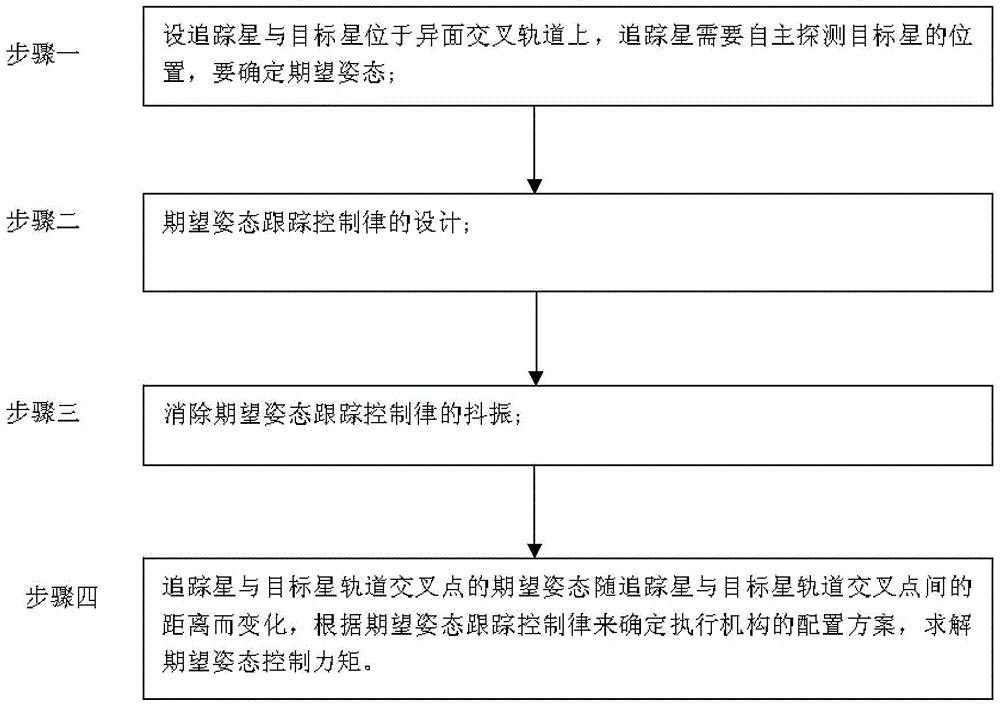
[0036] Specific embodiment one: combination figure 1 In this embodiment, the method for tracking fixed-time stable attitude pointing and tracking for different-plane crossing fast-changing orbits is characterized in that the method for tracking fixed-time stable attitude pointing and tracking for different-plane crossing fast-changing orbits specifically follows the following steps:
[0037] Step 1. Assuming that the tracking star and the target star are in a cross orbit on different planes, the tracking star needs to detect the position of the target star autonomously. In order to make the laser transmitter or observation equipment of the tracking star always point to the target star, first determine the desired attitude;
[0038] Step 2. Design of desired attitude tracking control law;
[0039] Step 3: Eliminate the chattering of the desired attitude tracking control law;
[0040] Step 4. The desired attitude of the orbital intersection of the tracking star and the target star varie...
specific Embodiment approach 2
[0041] Embodiment 2: This embodiment is different from Embodiment 1 in that it is characterized in that in the step 1, it is assumed that the tracking star and the target star are located in different cross orbits, and the tracking star needs to autonomously detect the position of the target. The laser transmitter or observation device of the tracking star always points to the target star. First, determine the desired attitude. The specific process is:
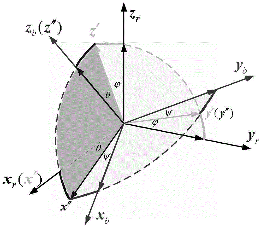
[0042] The unit vector of each coordinate axis of the desired attitude coordinate system is determined by the following formula in the inertial system:
[0043] i = r t - r c | r t - r c |
[0044] j = i × r c | i × r c | - - - ( 1 )
[0045] k=i×j
[0046] Where r t With r c Are the position vectors of the tracking star and the target star in the geocentric inertial coordinate system;
[0047] If the cosine transformation matrix of the d...
specific Embodiment approach 3
[0050] Specific embodiment three: This embodiment is different from specific embodiments one or two in that it is characterized in that the design of the desired attitude tracking control law in the second step, the specific steps are:
[0051] Calculate the desired attitude angle and the body attitude angle under the unit vector of each coordinate axis of the desired attitude coordinate system:
[0052] Record the desired attitude angle and the body attitude angle as a d And a b , Their difference is Euler's attitude angle error, denoted as e, that is, e=a b -a d , Let the system state be Can write linearized state equation
[0053] e ‾ e - - = 0 1 0 0 e e ‾ + 0 1 I ‾ ( u - a - - d I ) - - - ( 3 )
[0054] Where I is the principal inertia of the corresponding axis, and the expected angular acceleration of the attitude is bounded during a...
PUM
 Abstract
Description
Claims
Application Information
 - Generate Ideas
- Intellectual Property
- Life Sciences
- Materials
- Tech Scout
- Unparalleled Data Quality
- Higher Quality Content
- 60% Fewer Hallucinations
Browse by: Latest US Patents, China's latest patents, Technical Efficacy Thesaurus, Application Domain, Technology Topic, Popular Technical Reports.
© 2025 PatSnap. All rights reserved.Legal|Privacy policy|Modern Slavery Act Transparency Statement|Sitemap|About US| Contact US: help@patsnap.com


