Decompression shaft head face milling clamping mechanism

A technology of clamping mechanism and shaft end face, which is applied in the direction of clamping, metal processing machinery parts, support, etc., can solve the problems of high labor intensity and achieve the effect of high processing efficiency

Inactive Publication Date: 2015-04-22
重庆红旗缸盖制造有限公司
View PDF0 Cites 6 Cited by
  • Summary
  • Abstract
  • Description
  • Claims
  • Application Information

AI Technical Summary

Problems solved by technology

Due to the fact that different decompression shafts need to be clamped separately during milling, the labor intensity is high, and multiple clamping is required. For different decompression shafts, the positioning and machining accuracy are not nearly the same, so the same batch of Processed products bring different processing errors

Method used


Image

  • Decompression shaft head face milling clamping mechanism

Examples


Embodiment Construction

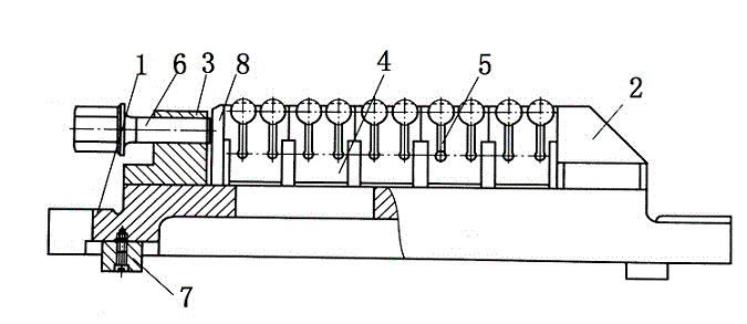
[0011] Such as figure 1 As shown, the decompression shaft end face milling clamping mechanism of the present invention includes a base 1, a stop 2 is provided at one end of the base 1, and a support block 3 is provided at the other end of the base 2, between the stop 2 and the support 3 Five elastic sliding blocks 4 are fixed, and the top surface of the elastic sliding block 4 is provided with two arc clamping grooves, and the arc of each arc clamping groove is greater than 180°. The elastic sliding block 4 is provided with an elastic clamping groove 5 communicating with the circular arc groove at the bottom of the circular arc groove. The support block 3 is provided with a horizontal threaded hole, and a compression screw 6 is screwed in the threaded hole. A pressing block 8 is arranged between the pressing screw 6 and the elastic sliding block 4. This arrangement can prevent the compression screw 6 from directly acting on the elastic slider 4, and can distribute the force, ...


PUM

PropertyMeasurementUnit
Radianaaaaaaaaaa

Abstract

The invention discloses a decompression shaft head face milling clamping mechanism. A workpiece to be processed is placed in a circular arc slot through the circular arc slot, because an elastic clamp slot communicated with the circular arc slot is opened in the bottom of the circular arc slot, and moreover, the radian of the circular arc slot is larger than 180 degrees, after the workpiece is placed in the circular arc slot, the workpiece would be clamped by a round slot. Through regulating a compression screw rod on a support block and extruding an elastic slide block through the compression screw rod, the deformation of the an elastic slot in the elastic slide block is reduced, and the round slot is driven to clamp the workpiece. Because each elastic slide block is provided with two elastic slots, at least two workpieces can be processed at one time, and moreover, the workpiece clamping precision and processing precision of each workpiece are basically the same, the processing error is the same, and the processing precision is not influenced. The processing efficiency is improved, and the labor intensity is lowered.

Description

Technical field [0001] The invention relates to a machining fixture, in particular to a milling and clamping mechanism for a pressure reducing shaft end face. Background technique [0002] Fixture is a process device used to quickly fasten parts during processing, so that machine tools, tools, and parts maintain the correct relative position. Tooling fixture is an indispensable part of machining. Driven by the development of machine tool technology towards high-speed, high-efficiency, precision, composite, intelligence, and environmental protection, fixture technology is developing in the direction of high-precision, high-efficiency, modular, combined, universal and economical. . Machine tool fixtures help ensure the accuracy of parts processing and stabilize product quality; help improve labor productivity and reduce costs; help improve workers' working conditions and ensure safe production; help expand the range of machine tools and realize "one machine with multiple uses". T...

Claims


Application Information

Patent Timeline
IPC IPC(8): B23Q3/06
CPCB23Q3/061
Inventor 刘小红
Owner 重庆红旗缸盖制造有限公司
Why Eureka
Try Eureka