Air flow drying system for catalyst production

A technology of airflow drying and airflow dryer, which is used in drying solid materials, drying, lighting and heating equipment, etc., can solve the problems of reduced illuminance and visibility, affecting the vision of indoor operation, reducing product quality and machine working accuracy, etc. The effect of protecting the environment

Inactive Publication Date: 2015-04-15
天津民祥医药销售有限公司
View PDF0 Cites 0 Cited by
  • Summary
  • Abstract
  • Description
  • Claims
  • Application Information

AI Technical Summary

Problems solved by technology

In addition, the dust discharged into the air will also reduce the product quality and the working accuracy of the machine. At the same time, the dust will also reduce the illuminance and visibility, and affect the vision of indoor operations.

Method used


Image

  • Air flow drying system for catalyst production
  • Air flow drying system for catalyst production

Examples


Embodiment Construction

[0010] In order to make the purpose, technical solutions and beneficial effects of the present invention more clear, the present invention will be further described in detail below in conjunction with the accompanying drawings and embodiments. It should be understood that the specific embodiments described here are only used to explain the present invention, and are not intended to limit the protection scope of the present invention.

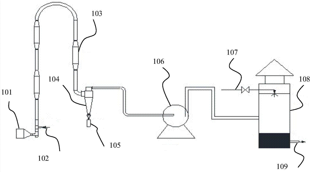
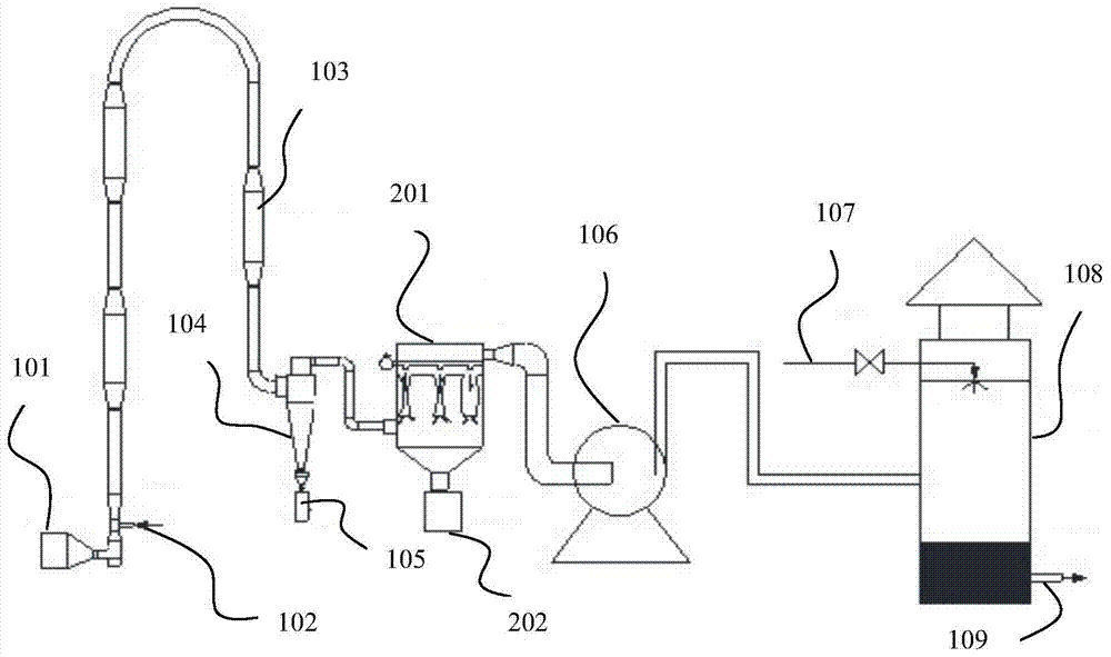
[0011] Such as figure 2 As shown, the present invention provides a kind of airflow drying system for catalyst production, comprising: heat source, airflow dryer, hot air separator, induced draft fan, tail gas absorption tower, and described heat source is connected with described airflow dryer through pipeline, The airflow dryer is connected with the heat source and the hot air separator, the hot air separator is connected with the airflow dryer and the induced draft fan, and the induced draft fan is connected with the hot air separator and the...


PUM


Abstract

The invention provides an air flow drying system for catalyst production. The air flow drying system comprises a heat source, an air flow dryer, a hot air separator, an induced draft fan and a tail gas absorption tower, the heat source is connected with the air flow dryer through a pipeline, the air flow dryer is connected with the heat source and the hot air separator, the hot air separator is connected with the air flow dryer and the induced draft fan, and the induced draft fan is connected with the hot air separator and the tail gas absorption tower. The air flow drying system is characterized in that a pulsed jet cloth filter is arranged between the hot air separator and the induced draft fan. The air flow drying system has the advantages that the pulsed jet cloth filter is additionally arranged on an air flow drying unit, tail gas passes the pulsed jet cloth filter and then enters the tail gas absorption tower, so that dust in the tail gas is basically adsorbed by the pulsed jet cloth filter, the tail gas is recovered, placed into a gelling unit and used, energy is saved, consumption is reduced, and environments are protected.

Description

technical field [0001] The invention belongs to the technical field of catalyst production, in particular to an airflow drying system used for catalyst production. Background technique [0002] Catalyst production is divided into raw material gelling, spray molding, roasting, washing, filtering, air drying, air classification and receiving and other units. After the catalyst is mixed evenly in the raw material gelling unit, it is dried and formed in the subsequent unit. The formed product (powder within 100 microns) is sucked by the induced draft fan and enters the roasting, washing, air-drying, and air-flow classification collection through the pipeline. unit. The exhaust gas produced by the airflow drying unit contains fine particles of dust, HCl gas, water vapor, and other substances. Such as figure 1 As shown, in the prior art, the tail gas directly enters the tail gas absorption tower for water washing, and the water washing absorbs the HCl gas, and some dust particl...

Claims


Application Information

Patent Timeline
Patent Type & Authority Applications(China)
IPC IPC(8): F26B25/00
Inventor 陈瑞香闫栋陈凯赵欣刘磊李金娜
Owner 天津民祥医药销售有限公司
Why Eureka
Try Eureka