
Dynamic ring detection tooling

A technology for detecting tooling and tooling, applied in workpiece clamping devices, manufacturing tools, etc., can solve problems such as clamping deformation of parts, and achieve the effects of reducing deformation of parts, improving detection efficiency, and convenient clamping

Inactive Publication Date: 2016-08-24
HARBIN
View PDF7 Cites 0 Cited by
  • Summary
  • Abstract
  • Description
  • Claims
  • Application Information

AI Technical Summary

Problems solved by technology

[0006] The purpose of the present invention is to provide a moving ring detection tool, which can solve the problem of clamping and deformation of parts, and perform reasonable and accurate positioning of parts

Method used


Image

  • Dynamic ring detection tooling
  • Dynamic ring detection tooling
  • Dynamic ring detection tooling

Examples


Embodiment Construction

[0013] The present invention will be described in further detail below.

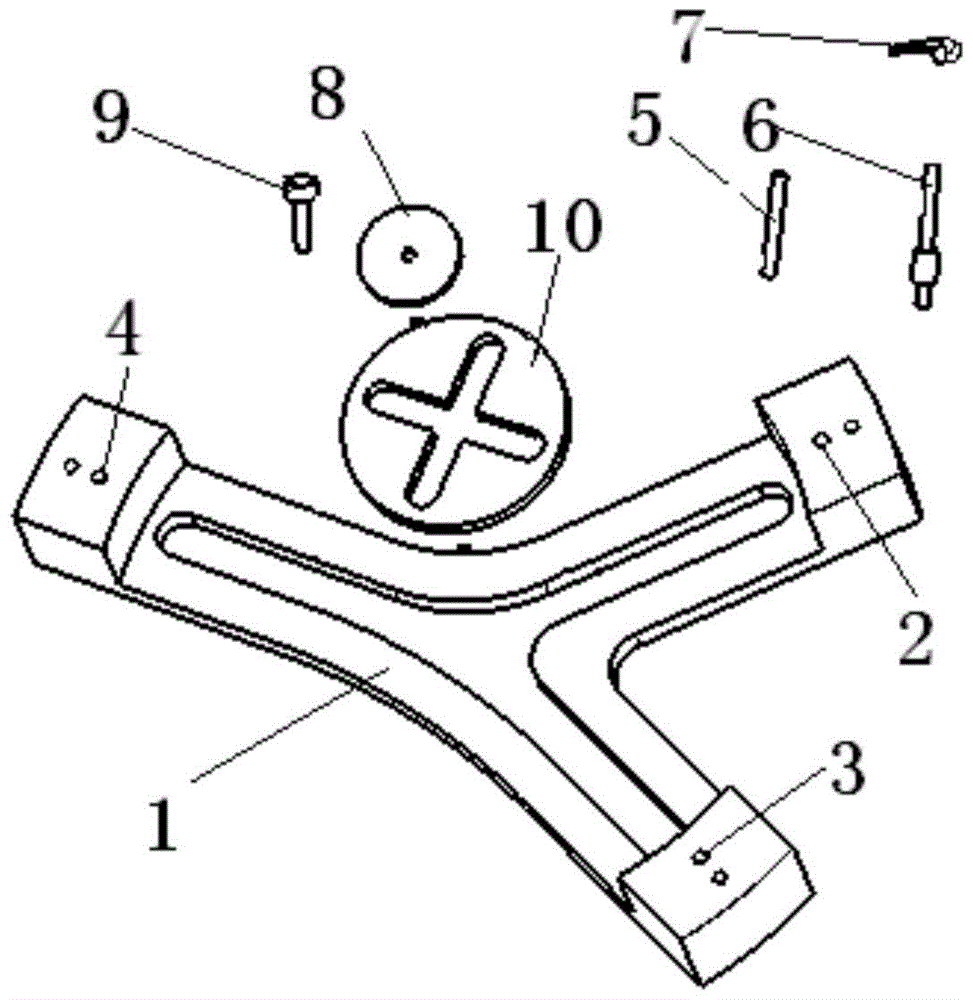
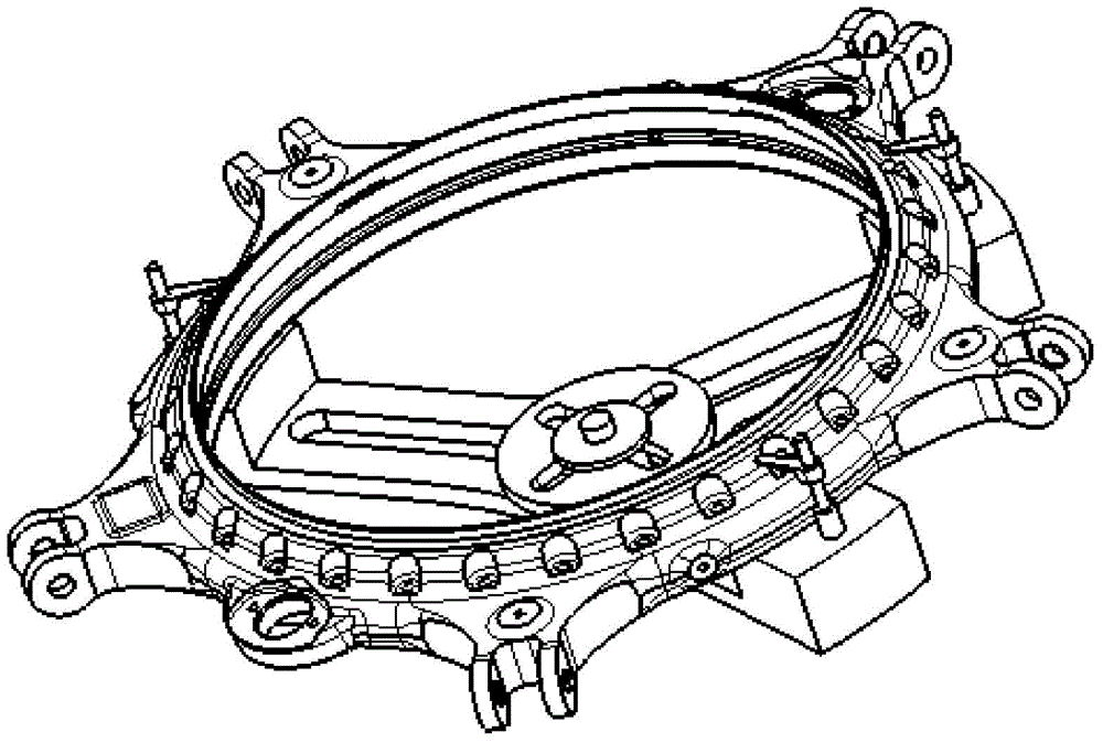
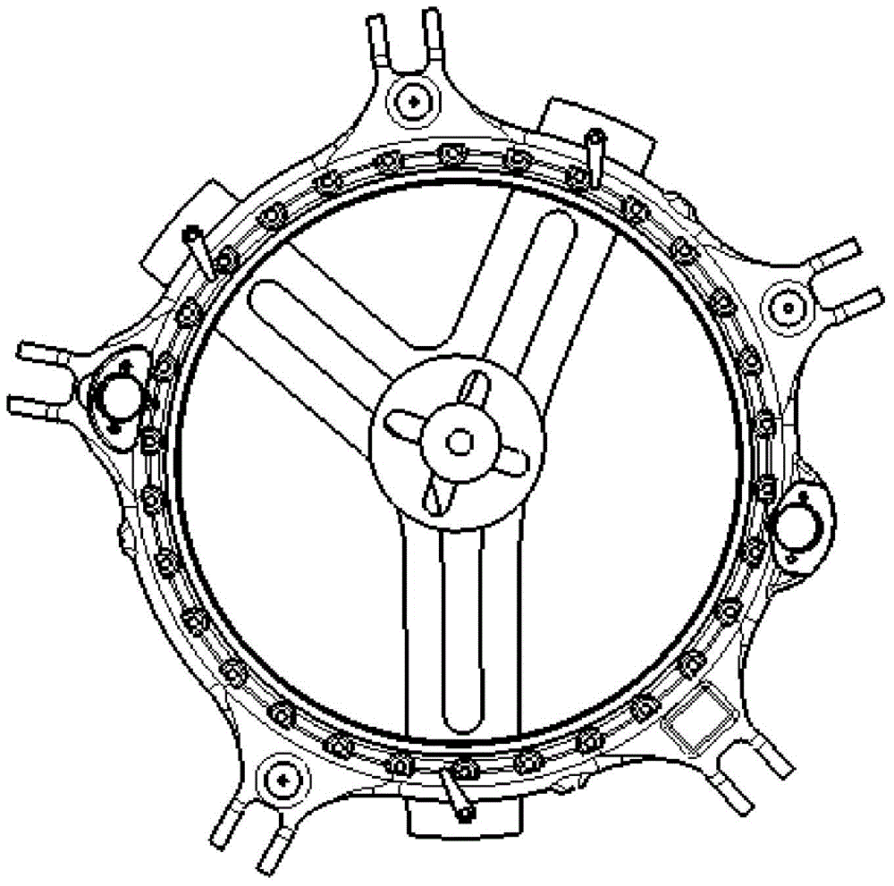
[0014] A moving ring detection tool, such as figure 1 , 2 , 3, including:

[0015] The tooling body, the tooling body 1 is in the shape of a "Y", the middle position of the upper surface of the left arm of the "Y" shape of the tooling body is provided with a first blind hole 2; the middle position of the upper surface of the right arm of the "Y" shape of the tooling body A second blind hole 3 is provided, and a third blind hole 4 is provided in the middle of the upper surface of the "Y" shaped third arm of the tooling body. The first blind hole, the second blind hole and the third blind hole cooperate with the moving ring Three reference holes penetrate the positioning pin 5, and the upper surface of the left arm, the right arm, and the third arm of the tool body "Y" are respectively provided with vertically upward elastic pressure plate support columns 6; the elastic pressure plate supports A medium-...


PUM


Abstract

The invention belongs to detection tooling; the invention provides a rotating seal ring detection tooling; the rotating seal ring detection tooling comprises a tooling body; the tooling body is'Y' shaped; the middle position on the upper surface of the left arm of the'Y' shaped tooling body is provided with a first blind hole; the middle position on the upper surface of the right arm of the'Y' shaped tooling body is provided with a second blind hole; the middle position on the upper surface of the third arm of the'Y' shaped tooling body is provided with a third blind hole; the first blind hole, the second blind hole and the third blind hole are matched with three benchmark holes of the rotating seal ring, and positioning pins are inserted therein; external sides on the upper surfaces of the left arm, the right arm and the third arm of the'Y' shaped tooling body are respectively provided with vertically upward elastic press plate supporting columns; the top portions of the elastic press plate supporting columns are provided with middle-sized elastic press plates; the middle-sized elastic press plates compress the position of the upper surface of the rotating seal ring with respect to the supporting surface; a clamp fastening screw passes through a through hole to tightly screw the tooling body on a worktable below the tooling body.

Description

technical field [0001] The invention belongs to a detection tool and relates to a moving ring detection tool. Background technique [0002] The moving ring is one of the key parts in the lift system of the helicopter. Its material is aluminum alloy, which has the characteristics of large size, high precision, many sizes to be tested, and long detection cycle, which requires high detection technology. In the past, there was no special inspection tool. The inspection method is to screw four support rods of equal height to the bottom plate, then place the moving ring on the four support rods of equal height, and cooperate with two pressure plates to complete the clamping of parts. After a period of time, The detection found that the original detection method has the following problems: [0003] 1) The preparation steps for clamping parts before testing are cumbersome and time-consuming, resulting in a waste of testing preparation time. [0004] 2) The clamping of the parts du...

Claims


Application Information

Patent Timeline
Patent Type & Authority Patents(China)
IPC IPC(8): B25B11/00
CPCB25B11/00
Inventor 方金超李长卫邓玉宝
Owner HARBIN
Learn More