Eureka AIR delivers breakthrough ideas for toughest innovation challenges, trusted by R&D personnel around the world.

Integrated power plant and data center

A technology for data centers and power stations, applied to electrical components, circuit devices, machines/engines, etc., to achieve the effects of reducing transmission and distribution losses, saving quantities, and eliminating energy losses

Inactive Publication Date: 2015-04-08
K2IP HLDG LLC
View PDF4 Cites 1 Cited by
  • Summary
  • Abstract
  • Description
  • Claims
  • Application Information

AI Technical Summary

Problems solved by technology

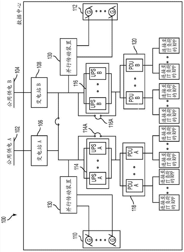
Moreover, the number and size of generators 110 and 112 is proportional to the electrical load and cooling load of the IT equipment, further inhibiting the development of high-density data centers because air permits and space requirements grow with the number and size of generators

Method used


Image

  • Integrated power plant and data center
  • Integrated power plant and data center
  • Integrated power plant and data center

Examples

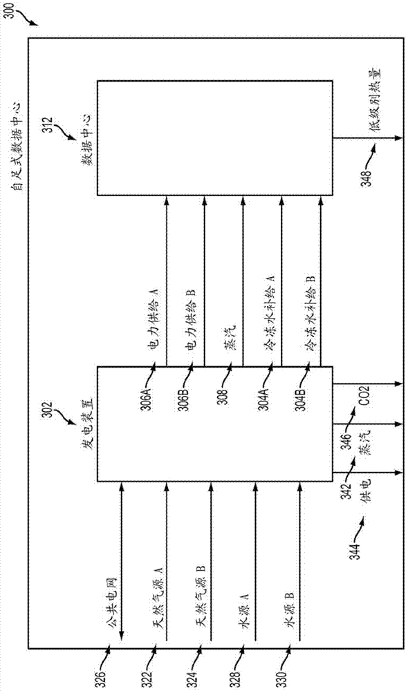

Embodiment Construction

[0025] A combined heat and power (CHP) station may include electrical and mechanical services. In terms of capacity, the generated electrical load and electrical cooling load demand of the data center can be balanced with respect to the electrical and mechanical supply of the CHP power plant and provide a total power plant efficiency of more than 75%. This high efficiency can be achieved, for example, by using selective heat recovery equipment for exhaust gas streams from turbines and engine power stations.

[0026] figure 2 It is a block diagram showing a system having a data center co-located with a combined heat and power (CHP) station according to an embodiment of the present disclosure. In the system 200 having the power station 302 co-located with the data center 312, the data center 302 may provide two independent electric service buses 306A and 306B. Power supply buses 306A and 306B may be coupled to substations 204A and 204B, respectively. The power distribution system...


PUM


Abstract

A power plant, in the form of a combined heat and power (CHP) plant, may be co-located with a data center to provide redundant electrical power. The CHP plant and the data center may operate as an island, separate from the local electrical-utility grid. The CHP plant may have a redundant fuel source connection to reduce unavailability of fuel for the CHP and increase the uptime of the data center. The CHP plant may include turbines and engines to manage variable loads within the data center. The power plant may include multiple distributions busses in high-availability configurations to provide highly-reliable and high-quality electricity to the data center. The positioning of these elements in the power plant design provides economies of scale and eliminates single points of failure commonly found in data center configurations, increasing the reliability of the data center.

Description

[0001] Cross references to related applications [0002] This application claims the right of priority to the U.S. Provisional Patent Application No. 61 / 655,205 entitled "COMBINATION HIGH AVAILABILITY CHP AND HIGH DENSITY DATA CENTER" filed on June 4, 2012, the entire contents of which are incorporated herein by reference. Technical field [0003] The present disclosure relates to power supplies. The present disclosure more specifically relates to redundant and highly reliable power supplies for data centers. Background technique [0004] The data center houses a large amount of information technology (IT) equipment, such as servers, data storage devices, and network equipment. The device has the ability to consume more than 600 watts per square foot (SF). In order to reduce the amount of real estate occupied by IT equipment, the equipment is stored in a rack or cabinet so that a large amount of equipment can be compressed in a smaller area. However, the current density of data c...

Claims


Application Information

Patent Timeline
IPC IPC(8): H02J3/24
CPCY02E20/16F01K23/10H02J4/00Y02E20/14Y10T307/305F01K13/02F01K13/00F01K17/02F01K17/04
Inventor R.克里兹曼E.E.克恩
Owner K2IP HLDG LLC
Why Eureka
Eureka Blog
Learn More