
Indexable insert for shoulder milling cutter and shoulder milling cutter with mounting cutouts for indexable inserts

A technology for indexing inserts and milling tools, applied in the field of indexable inserts for shoulder milling tools and shoulder milling tools with mounting cuts for the indexable inserts, can solve difficult contact surfaces, cutting edge Difficulty supporting indexable inserts, adequate settings, etc.

Inactive Publication Date: 2015-04-08
WALTER AG
View PDF7 Cites 11 Cited by
  • Summary
  • Abstract
  • Description
  • Claims
  • Application Information

AI Technical Summary

Problems solved by technology

[0006] In the case of DE 103 12 922 it is relatively difficult to produce suitable contact surfaces on indexable inserts and corresponding tools like e.g. shoulder milling tools, because the diagonal rise and fall of the corners cause helical Distorted top and bottom surfaces, making it difficult to support the corresponding indexable insert over a large surface area relative to the corresponding active cutting edge, even though a central flat recess is provided
In addition, the rectangular shape in the plane and the symmetrical configuration of the front and rear sides have the result that when using shoulder milling tools it is difficult to provide sufficient clearance angles both in the axial direction and also in the radial direction, which leads to Limitations in the maximum possible feed, or due to twists in the diagonal direction of the surface, require a greatly reduced rake surface where it is desirable to maintain a positive radial (as well as a positive axial) rake angle weakens the cutting edge

Method used


Image

  • Indexable insert for shoulder milling cutter and shoulder milling cutter with mounting cutouts for indexable inserts
  • Indexable insert for shoulder milling cutter and shoulder milling cutter with mounting cutouts for indexable inserts
  • Indexable insert for shoulder milling cutter and shoulder milling cutter with mounting cutouts for indexable inserts

Examples


Embodiment Construction

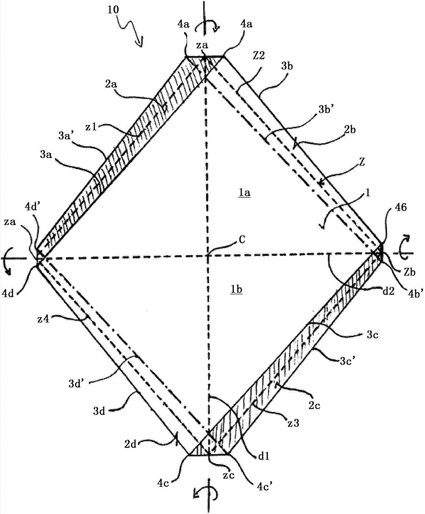
[0048] figure 1 The basic shape of the indexable insert according to the invention is shown in transparent view, in particular in plan view on the top side (which is identical to the plan view on the bottom side). All visible edges of the geometrical basic shapes are reproduced by solid lines, while lines that are hidden but are here rendered visible by means of a transparent view are shown as dotted lines. Finally, the dashed line shows a rhombus R inscribed in the indexable insert and defining a median plane Z Z , where the median plane Z can be imagined to coincide with the paper plane.

[0049] A rhombus is surrounded by its corner z a to z d Four sides z of equal length extending across or along the side surfaces 2a, 1b, 1c and 1d of the indexable insert and lying in a common plane referred to herein as the median plane Z 1 ,z 2 ,z 3 and z 4 across.

[0050] The top face 1 of this basic geometry of the indexable insert is formed by two triangular surfaces 1a and 1...


PUM


Abstract

Indexable insert has a non-rectangular parallelogram shape with nearly rhombic basic shape and an imaginary intermediate plane spanned by four corners of an imaginary rhombus with sides running at a distance away from the upper side and the underside along the peripheral lateral surface in a plane such that each equivalent cutting edge has the same variation of distance and angle from the intermediate plane. Two diagonally opposing corners of both the upper side and the underside each have a greater distance from the intermediate plane than do the respective diagonally opposing corners of the upper side and the underside lying therebetween, and the diagonally opposing corners of the upper side and of the underside are shifted parallel to the intermediate plane and, as viewed in a plan view onto the intermediate plane, in mutually opposite directions away from the associated diagonals of the rhombus spanning the intermediate plane.

Description

technical field [0001] The present invention relates to an indexable insert having a top surface and a bottom surface joined together by a peripherally extending side surface comprising a plurality of surface portions, wherein between these surface portions and the top and bottom surfaces At least some of the intersecting lines between each other form equivalent cutting edges with each other, and in plan view on the top and bottom faces, the indexable insert is correspondingly in the shape of a non-rectangular parallelogram with an almost rhombus basic shape And has an imaginary middle plane spanned by a rhombus, the sides of which extend along the periphery in a plane, and the side surfaces extend at intervals relative to the top and bottom surfaces, so that the equivalent of the top and bottom surfaces Each of the cutting edges has the same variation in spacing and angle with respect to the median plane spanned by the imaginary rhombus. [0002] The invention also relates t...

Claims


Application Information

Patent Timeline
IPC IPC(8): B23C5/20B23C5/10B23C5/06
CPCB23C2210/045B23C2200/165B23C2200/128B23C2200/164B23C2200/086B23C2200/085B23C2210/0457B23C2200/125B23C2200/0433B23C2210/168B23C5/207B23C5/06B23C5/202Y10T407/1924Y10T407/235
Inventor 于尔根·道布
Owner WALTER AG
Learn More