
Thermal relay temperature compensation structure

A thermal relay and temperature compensation technology, which is applied in the direction of circuits, electrical components, protective switch operation/release mechanisms, etc., can solve the problem of uncontrollable bending characteristics, damage to the molecular structure and physical properties of double gold, and the inability to ensure consistent tripping characteristics of thermal relays To improve the consistency of the tripping characteristics and achieve the effect of temperature compensation

Active Publication Date: 2017-03-22
ZHEJIANG CHINT ELECTRIC CO LTD
View PDF5 Cites 0 Cited by
  • Summary
  • Abstract
  • Description
  • Claims
  • Application Information

AI Technical Summary

Problems solved by technology

[0004] In the prior art, the U-shaped auxiliary double gold is stretched and bent during the stamping process, the internal molecular structure and physical properties of the double gold are destroyed, and its bending characteristics cannot be controlled. It is difficult to ensure its dimensional consistency and stability of bending characteristics during mass production. sex
This device also cannot guarantee the consistency of the tripping characteristics of the thermal relay under different temperature environments

Method used


Image

  • Thermal relay temperature compensation structure
  • Thermal relay temperature compensation structure
  • Thermal relay temperature compensation structure

Examples


Embodiment Construction

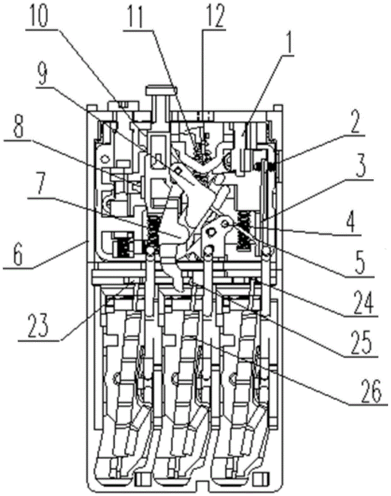
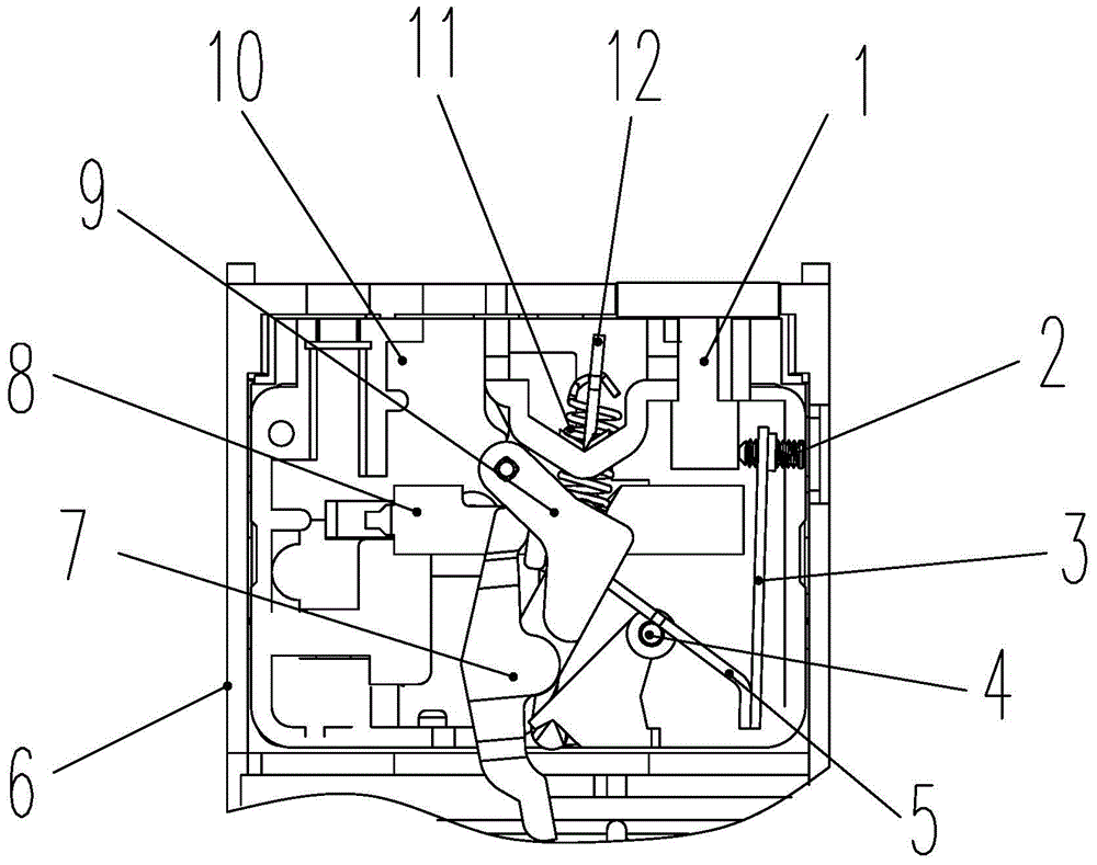
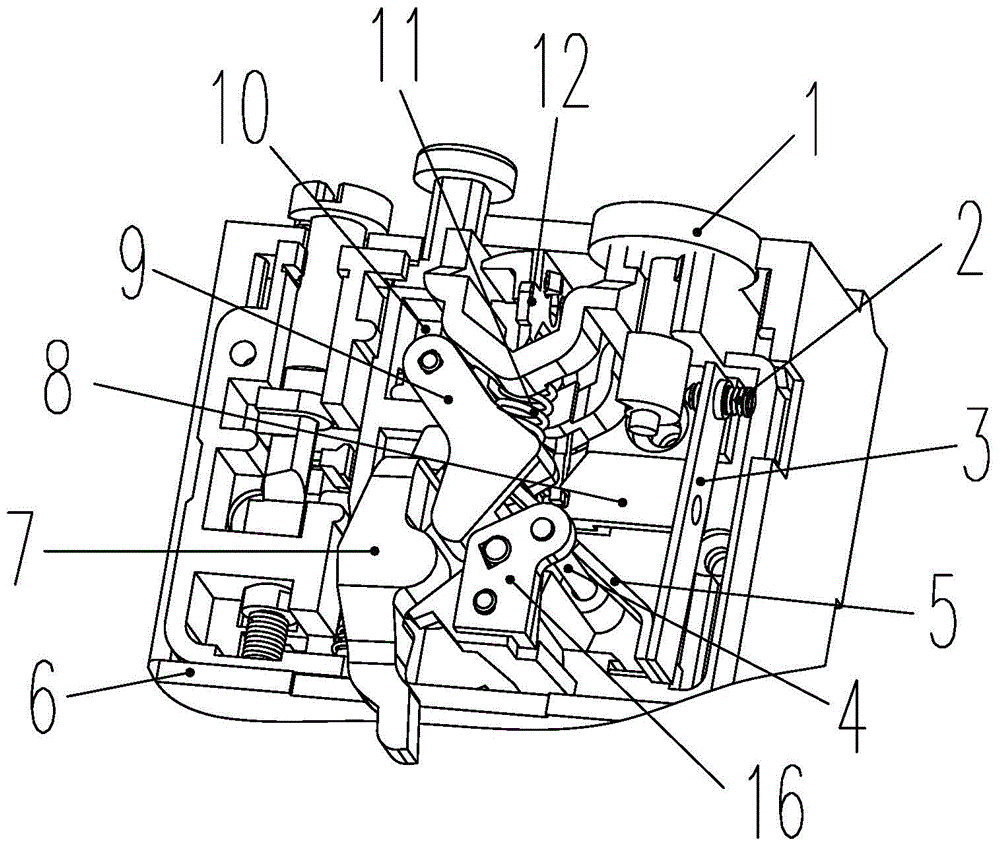
[0031] The following is attached Figures 1 to 17 The given examples further illustrate the specific implementation of the thermal relay temperature compensation structure of the present invention. The temperature compensation structure of the thermal relay of the present invention is not limited to the description of the following embodiments.

[0032] Such as Figure 1-5 As shown, the thermal relay temperature compensation structure of this embodiment includes a casing 6, and a support seat 10 is provided inside the casing 6. A tripping device connected to the main double metal 26 is provided on the support seat 10, and is in contact with the tripping device. The temperature compensating device includes a supporting member 5 and a straight auxiliary double gold 3, a rotating shaft 4 is fixed in the middle of the supporting member 5, and the rotating shaft 4 is installed on the supporting seat 10, and the supporting member 5 can rotate around the rotating shaft 4, and the su...


PUM


Abstract

The invention discloses a thermal relay temperature compensation structure comprising a shell which is provided with a supporting seat and a main bimetal inside. The supporting seat is provided with a tripping device connected with the main bimetal, and a temperature compensation device in contact fit with the tripping device. The temperature compensation device comprises a holder and a bar-shaped auxiliary bimetal. A rotating shaft is fixed to the middle position of the holder, and the rotating shaft is mounted on the supporting seat. The holder can rotate around the rotating shaft. One end of the holder is in contact fit with the tripping device, and the other end is rigidly connected with the auxiliary bimetal. The auxiliary bimetal of the thermal relay temperature compensation structure does not need to be stretched or bent, so that damage to the internal molecular structure and physical properties of the auxiliary bimetal is reduced. Therefore, the consistency of the tripping characteristic of thermal relays in different temperature environments can be enhanced.

Description

technical field [0001] The invention relates to the field of low-voltage electrical appliances, and more specifically relates to a temperature compensation structure of a thermal relay. Background technique [0002] Thermal relays are used to protect motors, and usually include heating components, main double-metal induction bending mechanisms, displacement transmission devices, contact breaking and closing devices, and housings. When the working current flowing through the motor is overloaded, the main double metal bends, and the state of the contact device is changed through the displacement transmission device, which is commonly referred to as tripping, to protect the motor. [0003] Considering that the product may be used in different temperature environments, the starting position of the main double gold is different. If the product is in different temperature environments and the motor flows the same overload current, the main double gold will have different bending ...

Claims


Application Information

Patent Timeline
Patent Type & Authority Patents(China)
IPC IPC(8): H01H71/16
CPCH01H71/162
Inventor 岳喜雷胡建国罗治钦
Owner ZHEJIANG CHINT ELECTRIC CO LTD
Learn More