
Pneumatic high-pressure grease filling machine

A technology of pneumatic high-pressure oiler, applied in the direction of engine components, engine lubrication, mechanical equipment, etc., can solve the problem of affecting the normal operation of the pneumatic high-pressure oiler, reducing the oil injection pressure of the pneumatic high-pressure oiler, and wasting a lot of time for disassembly and maintenance And other problems, to achieve the effect of good elasticity, faster oil feeding speed and long service life

Inactive Publication Date: 2015-04-08
ZHEJIANG REFINE WUFU AIR TOOLS
View PDF8 Cites 3 Cited by
  • Summary
  • Abstract
  • Description
  • Claims
  • Application Information

AI Technical Summary

Problems solved by technology

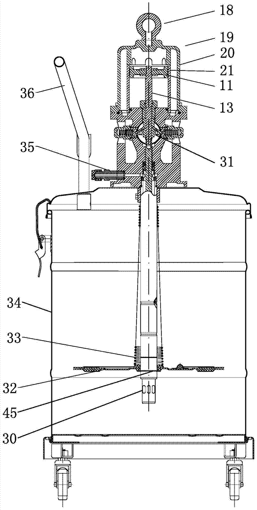
[0002] see figure 1 : Chinese patent CN 102506286B discloses a "pneumatic high-pressure oiler", in which a piston 7 connected to a piston rod 8 is arranged in the cylinder 1, and the up and down movement of the piston 7 drives the reversing valve 9, so that the high pressure from the air source The gas enters from the intake joint and passes through the reversing valve, and is alternately distributed to the upper chamber of the piston of cylinder 1 for intake, and the lower chamber of the piston for exhaust, and the gas allocated to the lower chamber of the piston of cylinder 1 for intake, and the upper chamber of the piston for exhaust, wherein: The reversing valve is connected with the upper cavity of the piston and the reversing valve through an external conduit and joint. or other objects collided to cause looseness or cracks and air leakage, which directly affects the normal operation of the pneumatic high-pressure oiler. At the same time, due to the thinner conduit, it affects the ventilation volume; in addition, it was found during use: the connecting pipe 4 connected to the lower side of the pump body seat And the spool on the valve on the lower part of the connecting rod assembly 5 connected to the piston rod 8 in the connecting pipe is a cylindrical spool made of metal material, if there are impurities such as sand grains in the butter, it is easy to get stuck between the valve seat and the valve. A pressure relief gap is formed between the cores 6, so that the pressure oil in the high-pressure chamber will leak from the pressure relief gap, resulting in a decrease in the maximum oil injection pressure of the pneumatic high-pressure oil injector, which will affect the oil injection efficiency in the slightest, and in severe cases for those that require high-pressure oil injection The part cannot complete the oiling task, and disassembly and maintenance need to waste a lot of time and energy. Repeated disassembly and assembly will also reduce the service life of the pneumatic high-pressure oiler and increase the production cost

Method used


Image

  • Pneumatic high-pressure grease filling machine
  • Pneumatic high-pressure grease filling machine
  • Pneumatic high-pressure grease filling machine

Examples


Embodiment Construction

[0025] Below in conjunction with accompanying drawing, the present invention will be further described with specific embodiment, see figure 2 -7:

[0026] Pneumatic high-pressure butter oiling machine, including barrel body 34 containing butter, oil injection pump set on barrel body 34, the reciprocating movement of piston rod 13 of the cylinder 19 of the oil injection pump drives the lifting plate 40 to pressurize the butter through the oil outlet joint 35 Sent out, the reciprocating movement of the piston rod 13 drives the reversing valve 31 alternately so that if the air supply port 16 of the reversing valve 31 is connected to the piston upper chamber 41 and the exhaust port is connected to the piston lower chamber 42, the air supply port 16 is connected to the piston lower chamber 42. It is connected with the piston lower chamber 42 and the exhaust port is connected with the piston upper chamber 41. The cylinder 19 includes an inner cylinder 21 and an outer cylinder 20 th...


PUM


Abstract

The invention belongs to the technical field of grease filling and relates to a pneumatic high-pressure grease filling machine comprising a barrel, a filling pump and a cylinder. The cylinder comprises an inner tube and an outer tube; the inner tube is internally provided with a piston connected with a piston rod; a vent gap is provided between the outer cylindrical face of the inner tube and the inner cylindrical face of the outer tube; an air inlet or air outlet of a reversing valve is communicated with an upper cavity of the piston through the vent gap; the air outlet or air inlet of the reversing valve is communicated with a lower cavity of the piston through an internal passage; a connecting pipe and a grease incoming casing are connected in order below a pump base of the filling pump; the inner wall of the connecting pipe above the grease incoming casing is provided with a grease incoming valve seat; a lifting rod unit is provided with a spool fitting the grease incoming valve seat; the pump base above a booster cavity formed by the pump base, the grease incoming casing, the connecting pipe, the grease incoming valve seat and the spool is provided with a grease outgoing connector. The pneumatic high-pressure grease filling machine has the advantages that the double-tube cylinder structure and the square spool are applied, failure rate of a product is low, grease filling is efficient, and the machine is suitable for grease filling of high-pressure grease filling parts.

Description

technical field [0001] The invention belongs to the technical field of butter oiling, in particular to a pneumatic high-pressure butter oiling machine. Background technique [0002] see figure 1 : Chinese patent CN 102506286B discloses a "pneumatic high-pressure oiler", in which a piston 7 connected to a piston rod 8 is arranged in the cylinder 1, and the up and down movement of the piston 7 drives the reversing valve 9, so that the high pressure from the air source The gas enters from the intake joint and passes through the reversing valve, and is alternately distributed to the upper chamber of the piston of cylinder 1 for intake, and the lower chamber of the piston for exhaust, and the gas allocated to the lower chamber of the piston of cylinder 1 for intake, and the upper chamber of the piston for exhaust, wherein: The reversing valve is connected with the upper cavity of the piston and the reversing valve through an external conduit and joint. or other objects collided...

Claims


Application Information

Patent Timeline
Patent Type & Authority Applications(China)
IPC IPC(8): F16N23/00F16N7/38
Inventor 潘灵钢陆志君李永刚邵先月
Owner ZHEJIANG REFINE WUFU AIR TOOLS
Learn More