
Quick Connect Assembly

A fast, component technology, applied in mechanical equipment, couplings, etc., can solve the problem that the male head of the quick connector cannot automatically release the pressure, etc., to ensure that the pressure is not crushed and the effect of automatic pressure relief is achieved.

Active Publication Date: 2016-12-07
CHINA AVIATION OPTICAL-ELECTRICAL TECH CO LTD
View PDF1 Cites 0 Cited by
  • Summary
  • Abstract
  • Description
  • Claims
  • Application Information

AI Technical Summary

Problems solved by technology

[0003] The purpose of the present invention is to provide a quick connector assembly to solve the problem in the prior art that the male head of the quick connector cannot automatically release pressure

Method used


Image

  • Quick Connect Assembly
  • Quick Connect Assembly
  • Quick Connect Assembly

Examples


Embodiment Construction

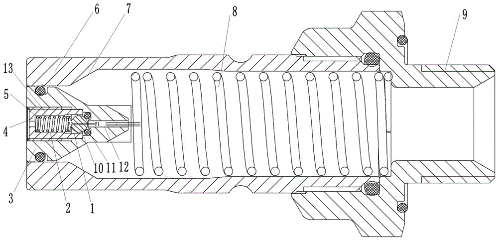
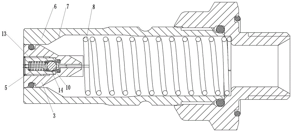
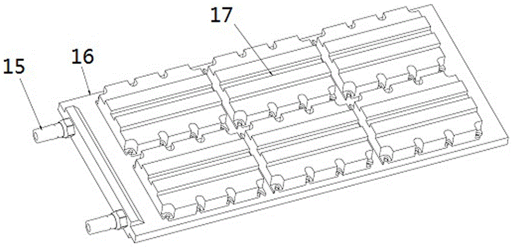
[0017] Examples of quick connector assemblies are Figure 1~5 Shown: including the quick connector female head and the quick connector male head, the quick connector female head includes a female head housing provided with a female head fluid channel, a female head valve core 30 is arranged in the female head fluid channel, and the periphery of the female head valve core The guide movement is equipped with a movable sealing sleeve 31, and the quick connector female head belongs to the prior art, and its specific structure is no longer described in detail. The quick connector male includes a male housing 6 whose front end is used to push the movable sealing sleeve of the quick connector female. The rear end of the male housing 6 is provided with an external thread 9 for connecting with the corresponding cold plate. There is a male head fluid channel that runs through the male head housing along the front and rear directions. The front end of the male head fluid channel guides a...


PUM


Abstract

The invention relates to a quick coupling assembly, which comprises a quick coupling female and a quick coupling male; the quick coupling male comprises a male shell; a male valve core is assembled in a male fluid flow passage of the male shell in a guide moving manner; a pressure relief passage used for communicating the male fluid flow passage with the outside atmosphere is arranged in the male valve core; the pressure relief passage comprises a liquid through hole section and a mounting hole section, wherein the liquid through hole section is connected with the male fluid flow passage, and the mounting hole section is connected with the outside atmosphere; a blocking piece is assembled in the mounting hole section in the guide moving manner; the male valve core is provided with a pressure relief spring used for applying an elastic acting force to the blocking piece so as to enable the blocking piece to block the liquid through hole section; a communicating passage used for communicating the liquid through hole section with the mounting hole section after the blocking piece is separated from the liquid through hole section is arranged on the blocking piece or the male valve core or between the blocking piece and the male valve core. The quick coupling male cannot automatically release pressure in the prior art is solved by the quick coupling assembly disclosed by the invention.

Description

technical field [0001] The present invention relates to a quick coupling assembly. Background technique [0002] In the liquid cooling system, the key component of heat dissipation is the cold plate. When in use, the heat-generating device is closely mounted on the cold plate, so as to achieve heat exchange with the cooling liquid flowing in the cold plate to obtain heat dissipation. Therefore, the cold plate The flatness of the cold plate is a key parameter. In actual use, it is necessary to use a quick connector assembly to pass coolant into the cold plate. The quick connector assembly includes an adapted quick connector male head and a quick connector female head. A quick connector male head connected to the inner cavity of the cold plate is arranged on the cold plate. When debugging, connect the quick connector female head to the quick connector male head, inject coolant into the inner cavity of the cold plate through the quick connector female head and the quick connec...

Claims


Application Information

Patent Timeline
Patent Type & Authority Patents(China)
IPC IPC(8): F16L37/36
CPCF16L37/36
Inventor 冯亚利李俊阳叶亚鹏
Owner CHINA AVIATION OPTICAL-ELECTRICAL TECH CO LTD
Learn More