
Numerical control wire saw processing machine

A processing machine and wire saw technology, which is applied in the field of CNC wire saw processing machines, can solve problems such as the inability to meet the processing requirements of modern high-precision precision parts, the application limitation of wire cutting technology, and rough surfaces, so as to improve cutting efficiency and movement direction And the effect of accurate speed, convenient lubrication and chip removal

Inactive Publication Date: 2015-04-08
NANTONG HENGLONG MACHINERY MFG
View PDF9 Cites 0 Cited by
  • Summary
  • Abstract
  • Description
  • Claims
  • Application Information

AI Technical Summary

Problems solved by technology

However, when using linear interpolation to process parts whose contours are circular arcs or oblique lines, the formed machining contours are actually realized by a series of stepped straight line segments along the X-axis and Y-axis directions from a microscopic point of view. Arc curves and oblique lines, the parts processed in this way have rough surfaces and poor finish, which cannot meet the processing requirements of modern high-precision precision parts, which limits the application of wire cutting technology in engineering to a certain extent.

Method used


Image

  • Numerical control wire saw processing machine
  • Numerical control wire saw processing machine
  • Numerical control wire saw processing machine

Examples


Embodiment Construction

[0028] The technical solutions of the present invention will be clearly and completely described below in conjunction with the accompanying drawings of the present invention. Apparently, the described embodiments are only some of the embodiments of the present invention, not all of them. Based on the embodiments of the present invention, all other embodiments obtained by persons of ordinary skill in the art without creative efforts fall within the protection scope of the present invention.

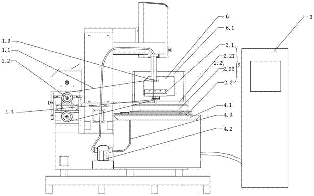
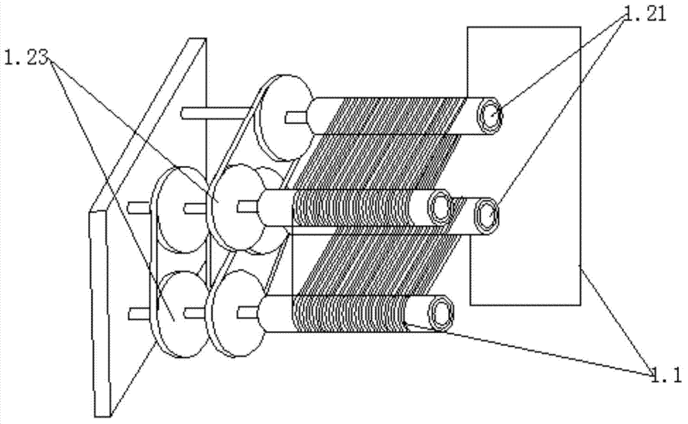
[0029] combine figure 1 As shown, a numerically controlled wire saw processing machine provided in this embodiment includes a wire storage system 1 , a workbench 2 , a control system 3 and a cutting fluid lubrication system 4 . The worktable 2 includes a rotary table 2.1, a linear moving table 2.2 and a base 2.3. The linear moving stage 2.2 includes an X-axis moving stage 2.21 and a Y-axis moving stage 2.22. The turntable 2.1 includes a support platform 2.11 and a bracket 2.12, and the b...


PUM

PropertyMeasurementUnit
lengthaaaaaaaaaa

Abstract

The invention provides a numerical control wire saw processing machine. The numerical control wire saw processing machine comprises a wire storage system, a workbench, a control system and a cutting fluid lubricating system, wherein the control system is connected with the cutting fluid lubricating system; the workbench comprises a revolving platform, a linear moving platform and a base; the linear moving platform is connected with the base in a sliding way; the revolving platform is arranged above the linear moving platform; the wire storage system comprises a cutting wire, a wire storage guide-wheel group, an upper wire rack and a lower wire rack; the upper wire rack and the lower wire rack are arranged above and below the outer side of the revolving platform respectively; the cutting wire is connected end to end, passes through the upper wire rack and the lower wire rack, and is wound on the outer side of the wire storage guide-wheel group; the control system is connected with the wire storage guide-wheel group, the revolving platform and the linear moving platform. An enclosed annular cutting wire is formed through end-to-end connection, so that one-way motion of the cutting wire is realized, and pause of the cutting wire is reduced; 360-degree rotation of a processed part can be realized through the revolving platform, and the motion direction of the workbench is consistent with the profile cutting direction of a workpiece, so that the smoothness of a processing face is ensured.

Description

technical field [0001] The invention relates to the field of mechanical manufacturing equipment, in particular to a numerically controlled wire saw processing machine. Background technique [0002] At present, the wire cutting machines on the market are all a drum, and the cutting wire is wound on the drum. As the cutting wire moves, the cutting wire moves from one end of the drum to the other. Due to the limited length of the cutting line, when the cutting line moves to its end, the rotation of the drum must be stopped, and then the cutting line is moved to the other end by the method of reverse rotation. Like this, the cutting movement will not be able to move continuously, so that the cutting wire has to move both from top to bottom and from bottom to top when cutting the workpiece. When the cutting line moves from bottom to top, it is difficult to lubricate the cutting line and remove chips. At the same time, the workbench of the wire cutting machine is a two-degree-o...

Claims


Application Information

Patent Timeline
Patent Type & Authority Applications(China)
IPC IPC(8): B28D1/02B28D5/04B28D7/00B28D7/02B23D61/18
CPCB23D57/0007B23D59/00B23Q11/08B23D57/0046B23D59/04B28D1/08B28D5/045B23D59/001B26D1/48B23D57/0053B26D7/088B23D57/003
Inventor 朱汉波
Owner NANTONG HENGLONG MACHINERY MFG
Learn More