
Capacitor lead welding bench

A wire welding and workbench technology, which is applied in welding equipment, auxiliary welding equipment, welding/cutting auxiliary equipment, etc., can solve problems such as inconvenient operation, and achieve the effects of reducing occupational diseases, reducing health damage, and ensuring physical health

Active Publication Date: 2015-04-08
SHANGHAI SIEYUAN CAPACITOR
View PDF10 Cites 2 Cited by
  • Summary
  • Abstract
  • Description
  • Claims
  • Application Information

AI Technical Summary

Problems solved by technology

[0003] The purpose of the present invention is to provide a capacitor lead wire welding workbench to solve the technical problem that capacitors of different heights need to be replaced with workbenches of different heights when welding the lead wires of the existing capacitors and the capacitor core, which is very inconvenient to operate

Method used


Image

  • Capacitor lead welding bench
  • Capacitor lead welding bench
  • Capacitor lead welding bench

Examples


Embodiment 1

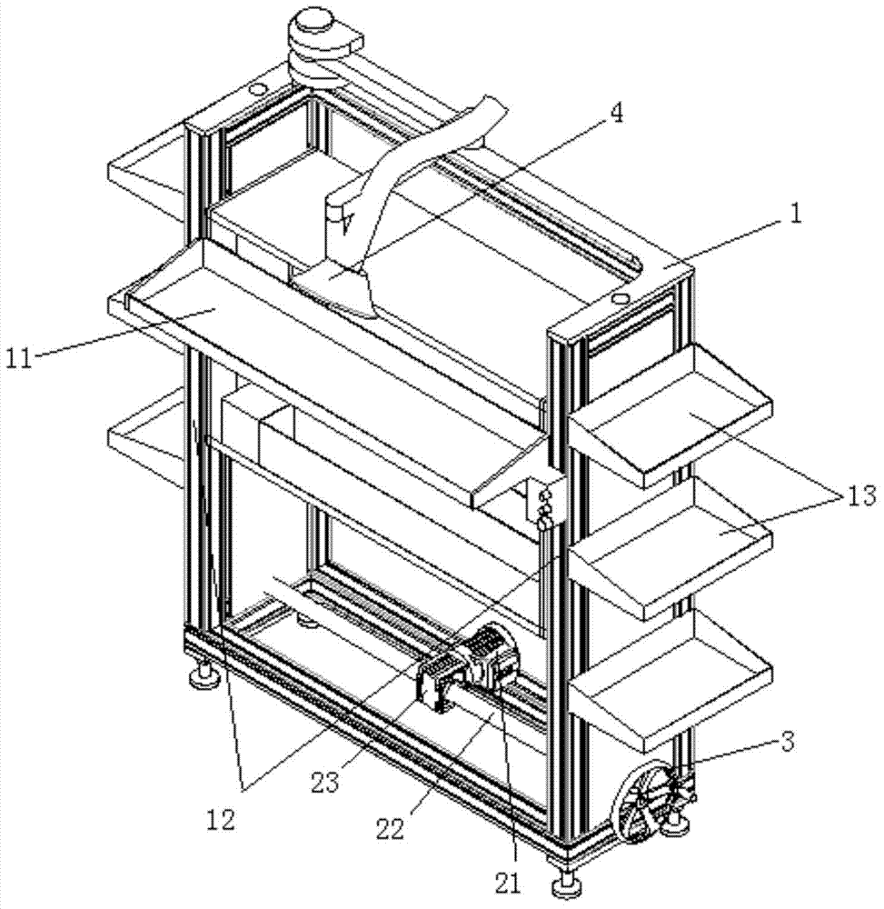
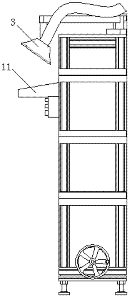
[0031] see Figure 1-3 , a capacitor lead wire welding workbench, including a frame body 1 and a control device, the frame body 1 is provided with at least two guide rails 12 and at least one worktable 11, the control device includes a controller, a servo motor 21, a speed reducer Machine 23, horizontal lead screw 22, gear I, gear II and vertical lead screw, described controller is connected with described servo motor 21, and described servo motor 21 is connected with described reducer 23, and described reducer 23 is connected with described reducer 23 The horizontal lead screw 22 is connected, the horizontal lead screw 22 is fixedly connected with the gear I, the gear I meshes with the gear II, the gear II is fixedly connected with the vertical lead screw, and the working The side of the table top 11 is provided with a connecting body, and the vertical lead screw is screwed with the internal thread of the connecting body. The work table 11 is provided with at least two slider...


PUM


Abstract

The invention provides a capacitor lead welding bench comprising a rack and a control device. At least two guide rails and at least one bench-top are arranged on the rack. The control device comprises a controller, a servo motor, a reducer, a horizontal screw, a gear I, a gear II and a vertical screw; the controller is connected with the servo motor; the servo motor is connected with the reducer; the reducer is connected with the horizontal screw; the horizontal screw is fixedly connected with the gear I; the gear I meshes with the gear II; the gear II is fixedly connected with the vertical screw; a connecting member is disposed on each bench-top; the vertical screw is screwed to an internal thread of the connecting member; at least two sliders are arranged on each bench-top; the sliders can move up and down along the guide rails. Compared with the prior art, the capacitor lead welding bench has the advantages that the height of each bench-top of the bench can be adjusted as required, the bench is conveniently applied to welding of leads of different specifications of capacitors, operators need not change the bench, and operating efficiency is improved.

Description

technical field [0001] The invention relates to the technical field of capacitor lead welding, in particular to a capacitor lead welding workbench applied to capacitor lead welding. Background technique [0002] In the capacitor manufacturing process, the lead welding of the capacitor is an extremely important process, which mainly realizes the welding and fixing of the lead wire and the capacitor core. At present, the lead wire welding of capacitors mostly relies on manual work. Generally, the capacitor is placed on the bracket first, and then the capacitor core is placed on a workbench with a suitable height, and then the lead wires of the capacitor and the capacitor core are welded and fixed. When the height of the machine is different, it is necessary to choose a workbench of different height, which is very inconvenient to operate. Contents of the invention [0003] The purpose of the present invention is to provide a capacitor lead wire welding workbench to solve the...

Claims


Application Information

Patent Timeline
Patent Type & Authority Applications(China)
IPC IPC(8): B23K37/00
CPCB23K37/00B23K2101/36
Inventor 隋海玉宗奎田小群
Owner SHANGHAI SIEYUAN CAPACITOR
Learn More