
Message boundary positioning method and device oriented to plate-grade multi-channel parallel bus

A multi-channel, message technology, applied in the direction of digital transmission system, electrical components, error prevention, etc., can solve the problems of increasing the number of single-ended signal lines, increasing the number of chip board-level connections, affecting the bus bandwidth, etc., to achieve reduction Limitation of transmission frequency increase, reduction of control information load, effect of increasing effective data load

Active Publication Date: 2015-04-01
NAT UNIV OF DEFENSE TECH
View PDF5 Cites 1 Cited by
  • Summary
  • Abstract
  • Description
  • Claims
  • Application Information

AI Technical Summary

Problems solved by technology

[0003] Although the multi-channel parallel bus can improve bandwidth by adopting double data rate technology and multi-channel technology, its disadvantage is that the transmission clock frequency cannot be infinitely improved due to the narrowing of the data sampling window, and multi-channel transmission inevitably increases the number of single-ended signals. The number of wires leads to a multiplied increase in the number of output pads of the chip and the number of board-level connections, which causes great difficulties in chip packaging design and board-level wiring.
In order to solve this problem, the current main technical routes are: (1) Sampling data at a higher data rate, such as the Quad Data Rate (QDR) sampling technology that has not yet become mainstream. The frequency sampling data, the bandwidth can be increased by four times, but the sampling window size is reduced to four times the original, the physical implementation is very difficult, so there are very few related products based on QDR technology, and the typical DIMM memory based on QDR technology uses QDR technology For data transmission, a QDR-based inter-chip transmission bus is used between the IBM Power7 chip and the off-chip memory controller, but QDR has not yet become the mainstream in the general market; (2) A combination of serial and parallel technologies is used, and differential signals Data is transmitted serially, but an independent source synchronous clock line is used to transmit the clock to reduce the additional delay overhead caused by the clock encoding and decoding process in the pure serial bus. Typically, AMD's HyperTransport bus adopts this method
(3) Architecture-level message format optimization. On the premise that the transmission bandwidth meets the requirements, by dividing the long-bit-width message into multiple short-bit-width flits (Flit), the data transmitted on the transmission bus is divided into flits. The main problem of this method is that a message needs multiple clock cycles to pass through the bus, and the boundary of the message must be correctly positioned to ensure that the receiver assembles the correct message
The traditional method needs to add additional physical frame (frame) identification, message header (head) identification and message tail (tail) identification for each microchip, resulting in additional control information load and reducing the utilization of bus bandwidth, especially For the multi-channel parallel bus, additional information requires additional data lines for transmission, which increases the number of chip PAD pins and board-level interconnection lines, increases the difficulty of chip physical design and board-level layout and wiring, and reduces The size of the data sampling window limits the improvement of the transmission frequency, which ultimately affects the improvement of the bus bandwidth

Method used


Image

  • Message boundary positioning method and device oriented to plate-grade multi-channel parallel bus
  • Message boundary positioning method and device oriented to plate-grade multi-channel parallel bus
  • Message boundary positioning method and device oriented to plate-grade multi-channel parallel bus

Examples


Embodiment Construction

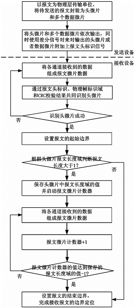
[0047] Such as figure 1 As shown, the implementation steps of the message boundary positioning method for the board-level multi-channel parallel bus in this embodiment are as follows:

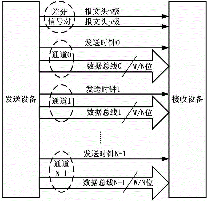
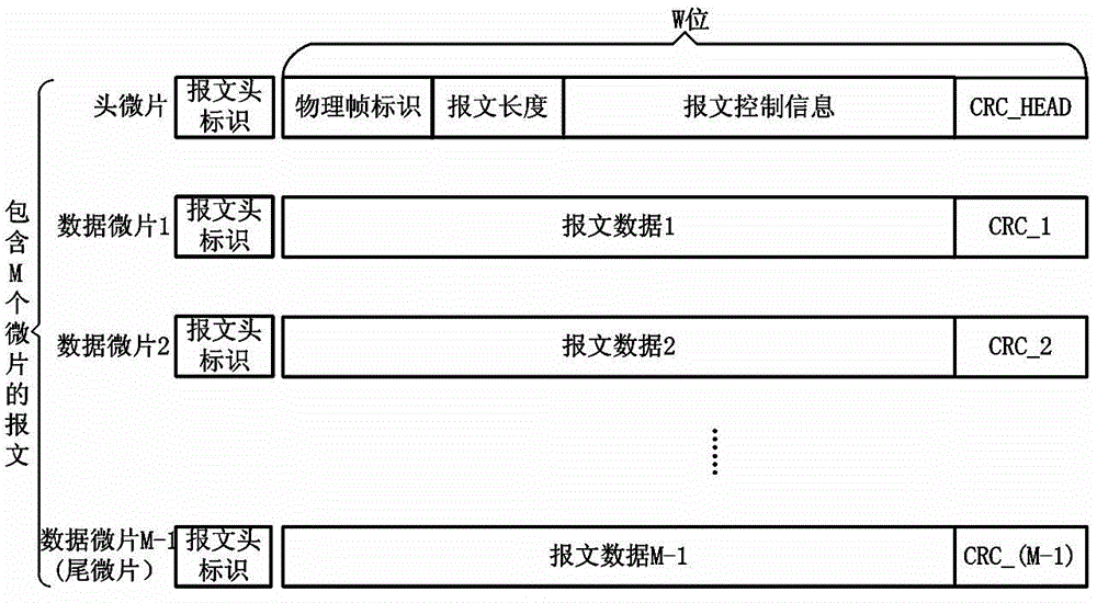
[0048] 1) Taking the message as the basic unit of bus physical layer transmission, the header flakes and multiple data flakes that constitute the message are sequentially output, and the message length field in the header flakes records the data of a complete message The number of microchips, and additionally use a differential signal pair composed of two signal lines to add a message header identification signal to the output header microchip or data microchip;

[0049] 2) The data received by each channel is composed of message microchip data, and the header microchip is identified according to the received message header identification signal and message microchip data. If the header microchip is successfully identified, the initial boundary of the message is set And start the preset messag...


PUM


Abstract

The invention discloses a message boundary positioning method and device oriented to a plate-grade multi-channel parallel bus. The method comprises the following steps: packaging a message into a head flit and a plurality of data flits; by taking the message as a basic unit of transmission of a bus physical layer, sequentially outputting the head flit and the plurality of data flits; adding a message header mark signal by using a differential signal pair; after receiving message flit data by a receiver, identifying the head flit by the message header mark signal and the message flit data; if the head flit is successively identified, counting; setting a finishing boundary of the message according to the counting to finish boundary positioning of the received message. The device comprises a message data transmitting unit and a message data receiving unit, which correspond to the method. By virtue of the message boundary positioning method and device, extra control information loads are reduced as a whole and the utilization rate of bus bandwidth is improved; the physical designing and wiring difficulty of chips is reduced and the bus bandwidth is improved; on the other hand, the reliability of message boundary positioning can be improved and the positioned message has an accurate message format.

Description

technical field [0001] The invention relates to the technical field of board-level multi-channel parallel bus architecture design, in particular to a message boundary positioning method and device for board-level multi-channel parallel bus. Background technique [0002] With the development of high-performance servers and ultra-large-scale computers, system designers have higher and higher requirements for board-level high-speed transmission buses. How to make data transmission delays between chips smaller and bandwidth higher is an important problem that needs to be solved. The traditional parallel bus technology uses a single-end (single-end) signal line to transmit data. A clock signal line and several parallel data signal lines transmit signals from the sender to the receiver at the same time. The receiver uses the clock signal to control the read data signal. Sampling, when the transmission frequency increases to a certain extent, due to the delay skew between the data ...

Claims


Application Information

Patent Timeline
IPC IPC(8): H04L12/70H04L29/06H04L1/00
Inventor 周宏伟邓让钰李永进晏小波张英杨乾明冯权友曾坤戴泽福王勇窦强
Owner NAT UNIV OF DEFENSE TECH
Learn More