
Method for measuring longitudinal wave velocity of anisotropic material

An anisotropy and measurement method technology, which is applied in the analysis of solids using sound waves/ultrasonic waves/infrasonic waves, can solve problems such as complex measurement steps, low measurement accuracy, and low amplitude of reflected echo signals, and shorten the measurement period. Effects of measurement accuracy and simplification of measurement procedures

Active Publication Date: 2015-04-01
AVIC BEIJING INST OF AERONAUTICAL MATERIALS
View PDF5 Cites 10 Cited by
  • Summary
  • Abstract
  • Description
  • Claims
  • Application Information

AI Technical Summary

Problems solved by technology

The traditional method of ultrasonic measurement of sound velocity is mostly realized by the reflection method of a single probe or the penetration method of a pair of probes. Due to the sound velocity directionality of anisotropic materials, when measuring the sound velocity at different propagation angles, it is necessary to use a computer-controlled measuring method. The angle of incidence is constantly adjusted by using a horn, and the water temperature is stabilized by means of a water immersion circulating pump. At the same time, due to the influence of mode conversion and reflection / transmission coefficient, the amplitude of the reflected echo signal is relatively low (such as Li Jiawei, Chen Jimao. Nondestructive Testing Handbook [ M]. Beijing: Machinery Industry Press, 2002, p238)
Its disadvantages are: complex measurement steps, long measurement cycle and low measurement accuracy

Method used


Image

  • Method for measuring longitudinal wave velocity of anisotropic material
  • Method for measuring longitudinal wave velocity of anisotropic material
  • Method for measuring longitudinal wave velocity of anisotropic material

Examples


Embodiment 1

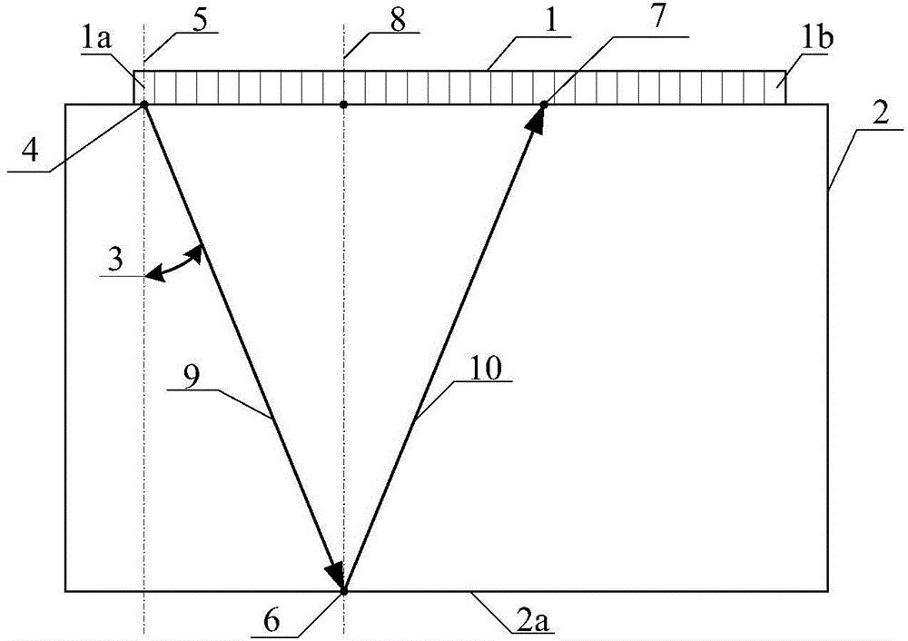
[0069] In this embodiment, a carbon fiber-reinforced epoxy resin-based composite laminate sample is taken as an example to describe in detail the measurement method of the longitudinal wave sound velocity. The thickness of the tested sample is H=10mm, and the measurement steps are as follows:

[0070] 1. Ultrasonic echo data acquisition and storage: select a phased array ultrasonic linear array probe, the number of array elements N=32, the array element spacing p=0.6mm, and the array element width a=0.5mm; the phased array ultrasonic linear array The probe is placed on the upper surface of the tested sample after smearing the coupling agent, and the position of the phased array ultrasonic linear array probe is not moved during the measurement of the longitudinal wave sound velocity; the phased array ultrasonic flaw detector is set so that the phased array ultrasonic linear array probe The No. 1 to No. 3 array element chips from the left end emit ultrasonic waves sequentially. A...


PUM


Abstract

The invention belongs to the technical field of the nondestructive detection, and relates to improvement of a method for measuring a longitudinal wave velocity of an anisotropic material by adopting an ultrasonic probe. The method is characterized in that a phased-array ultrasonic linear array probe is adopted to measure the longitudinal wave velocity. The method comprises the following steps: acquiring and storing ultrasonic echo data; acquiring a bottom wave propagation time data group of an ultrasonic echo signal; calculating a bottom wave propagation time average value data group; calculating sound wave shortest-path propagation angle data group and a sound wave shortest propagation path data group; calculating a longitudinal wave velocity data group corresponding to each sound wave shortest-path propagation angle; and establishing an analysis function of the longitudinal wave propagation velocity V and the sound wave propagation angle theta. According to the improved method for measuring the longitudinal wave velocity of the anisotropic material, the measurement steps are simplified, the measurement period is shortened, and the measurement precision is improved.

Description

technical field [0001] The invention belongs to the technical field of non-destructive testing and relates to the improvement of a method for measuring the sound velocity of longitudinal waves of anisotropic materials by using an ultrasonic probe. Background technique [0002] Ultrasonic testing is to study the reflected, transmitted and scattered waves through the interaction of ultrasonic waves with the tested sample, to measure the geometric characteristics of the sample, to detect macroscopic defects, to detect and characterize changes in tissue structure and mechanical properties, and to further analyze its A technique for evaluating the performance of a specific application. Conventional ultrasonic probes used in ultrasonic testing usually have two types in terms of the number of chips: one contains only one chip, which is used for both transmitting and receiving ultrasonic waves; the other contains a pair of chips, and one chip is used for transmitting Ultrasound, an...

Claims


Application Information

Patent Timeline
IPC IPC(8): G01N29/07
Inventor 徐娜王东升梁菁岳翔李硕宁
Owner AVIC BEIJING INST OF AERONAUTICAL MATERIALS
Learn More