
A Rolling and Sliding Mixed Friction Stepless Speed ​​Adjuster

A technology of stepless speed control box and mixed friction, which is applied in the direction of transmission, transmission control, and components with teeth, etc. It can solve the problems of reduced magnetic field strength of permanent magnets, temperature sensitivity of permanent magnets, and restricted speed regulation performance. Achieve good braking effect, increase friction area, and superior explosion-proof performance

Inactive Publication Date: 2016-09-14
HUNAN YUANYANG COAL MACHINE MFG
View PDF6 Cites 0 Cited by
  • Summary
  • Abstract
  • Description
  • Claims
  • Application Information

AI Technical Summary

Problems solved by technology

Its advantages are safety, reliability, and energy saving; low failure rate and less maintenance; its disadvantages: permanent magnets are sensitive to temperature, poor thermal stability, demagnetization when the ambient temperature exceeds a certain value, and knocking will also affect magnetism. The magnetic field strength of the magnet will also decrease
Not only seriously restricts its speed regulation performance, but also brings certain safety hazards when used in mines

Method used


Image

  • A Rolling and Sliding Mixed Friction Stepless Speed ​​Adjuster
  • A Rolling and Sliding Mixed Friction Stepless Speed ​​Adjuster

Examples


Embodiment Construction

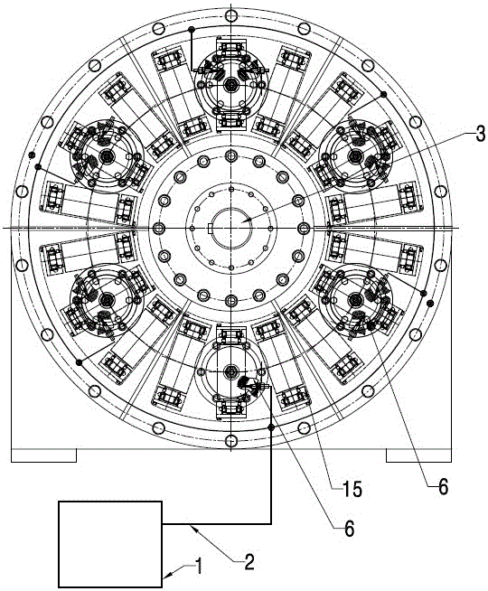
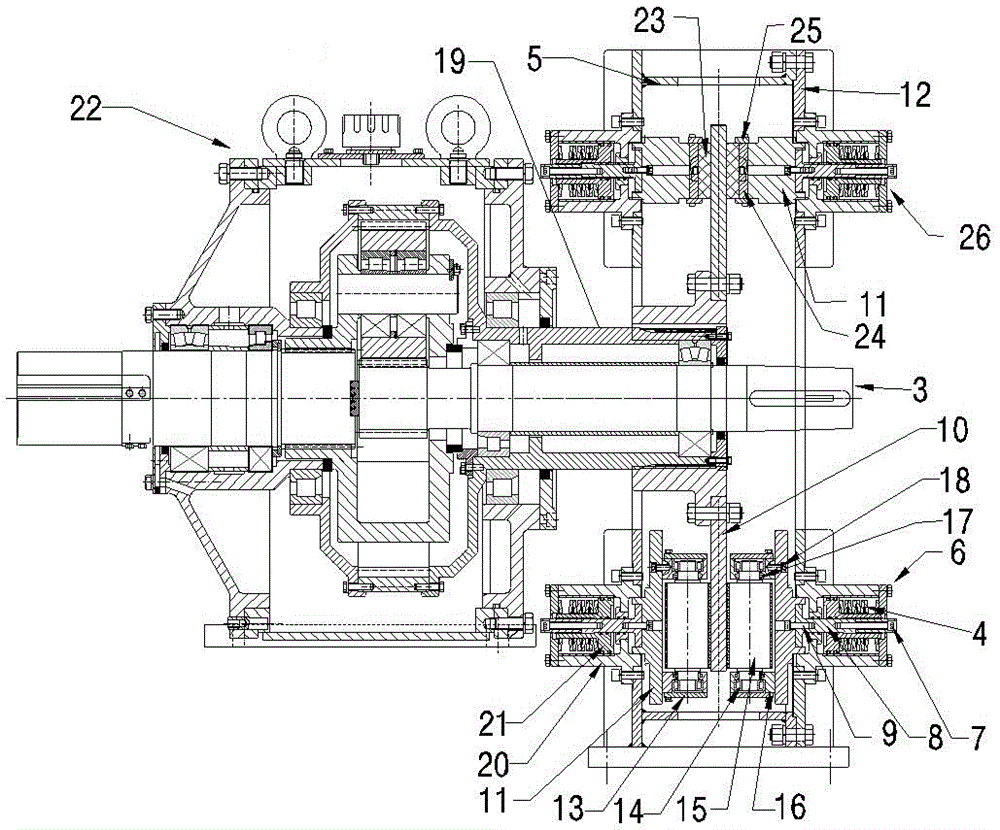
[0035] Such as Figure 1~2 As shown, a rolling and sliding mixed friction stepless speed regulating box includes a planetary differential reducer 22, a flywheel 10 installed on the exposed rotating shaft 19 of the planetary differential reducer, and a flywheel symmetrically installed 10. Six pairs of disc brakes on both sides to adjust the speed of the flywheel;

[0036] Described disc brake comprises rolling disc brake 6 and sliding disc brake 26, and rolling disc brake 6 comprises piston cylinder 20, piston rod 8, and the piston 21 that piston rod 8 rear end is fixedly connected, and piston 21 is positioned at piston cylinder 20. Disc spring 4 is installed inside and on its outer wall, and one end of disc spring 4 is fixedly connected with the cylinder head of the piston cylinder, and the piston 21 is pushed to move through the pre-compressed disc spring 4, thereby pushing the piston rod 8 to move axially.

[0037]The front end of the piston rod 8 of the rolling disc gate 6...


PUM


Abstract

The invention discloses a rolling and sliding mixed friction stepless speed regulating box, comprising a differential planetary gear reducer, a speed regulating wheel and at least one pair of disc brakes, wherein the speed regulating wheel is arranged on an exposed rotating shaft of the differential planetary gear reducer; the pair of disc brakes is symmetrically arranged on two side surfaces of the speed regulating wheel and is used for adjusting the rotating speed of the speed regulating wheel; each disc brake comprises a rolling disc brake and a sliding disc brake; the front end of a piston rod of each rolling disc brake is connected with a wear-resisting roller through a guide pressure plate; each wear-resisting roller is fixed on the corresponding guide pressure plate through a bearing block and a bearing; the wear-resisting rollers are symmetrically distributed on two sides of the speed regulating wheel and are close to the speed regulating wheel; the axes of the wear-resisting rollers are parallel to the radial direction of the speed regulating wheel; the front end of the piston rod of each sliding disc brake is connected with a brake block through the corresponding guide pressure plate; the brake blocks are symmetrically distributed on two sides of the speed regulating wheel in pairs, are close to the speed regulating wheels, and are vertical to the side surface of the speed regulating wheel. According to the speed regulating box, single brake block brake is replaced with the wear-resisting rollers and the brake blocks; a cantilever bracket type disc brake is replaced with a flange type fastening disc brake; the rolling and sliding mixed friction stepless speed regulating box has the advantages of small calorific value, good explosion-proof performance and simple structure.

Description

technical field [0001] The invention belongs to the technical field of stepless speed regulation of equipment, and in particular relates to a rolling and sliding mixed friction stepless speed regulation box. Background technique [0002] In the work of high-power mechanical equipment, it is necessary to consider the problem of stable stepless speed regulation caused by the change of working conditions. In-depth and extensive research on stepless speed regulation technology has been carried out in multidisciplinary fields such as machinery, electrical machinery and electronics, hydraulic power and hydraulic pressure at home and abroad, and various speed regulation devices or equipment have been developed. Currently on the market, there are old-fashioned hydraulic coupling governors, hydraulic governors, American CST governors, frequency conversion governors and the latest British permanent magnet governors. Although these variable speed transmissions have their own character...

Claims


Application Information

Patent Timeline
Patent Type & Authority Patents(China)
IPC IPC(8): F16H37/08F16H61/30F16H61/664
CPCF16H37/08F16H61/30F16H61/664
Inventor 李本平李达王伏林阳芳南肖建群
Owner HUNAN YUANYANG COAL MACHINE MFG
Learn More