
Prefabricated part sweeping and oil spraying machine

A technology of prefabricated components and fuel injection machines, which is applied in the direction of spraying devices, spraying devices, manufacturing tools, etc. It can solve the problems of consuming a lot of time, manpower and material resources, the cleaning device is insufficient, and the oil film spraying is uneven, so as to achieve simple maintenance and easy work , low cost effect

Inactive Publication Date: 2015-04-01
NORTHERN HEAVY IND GRP CO LTD
View PDF5 Cites 3 Cited by
  • Summary
  • Abstract
  • Description
  • Claims
  • Application Information

AI Technical Summary

Problems solved by technology

Based on the understanding of the production technology of the concrete prefabricated component equipment manufacturing industry at home and abroad, it is found that the oil spraying process before the concrete construction tray enters the kiln body and the cleaning tray process after leaving the kiln require two types of equipment that occupy a large area to operate, and It consumes a lot of time, manpower and material resources, and is often accompanied by problems such as uneven oil film spraying and unclean pallet cleaning.
However, all production equipment manufacturers have not effectively solved this problem, especially in the production process of concrete prefabricated components, when there are two processes of feeding pallets and taking out pallets at the same time, a single oil injection device or a single cleaning device appears to be a problem. overwhelmed

Method used


Image

  • Prefabricated part sweeping and oil spraying machine
  • Prefabricated part sweeping and oil spraying machine
  • Prefabricated part sweeping and oil spraying machine

Examples


Embodiment Construction

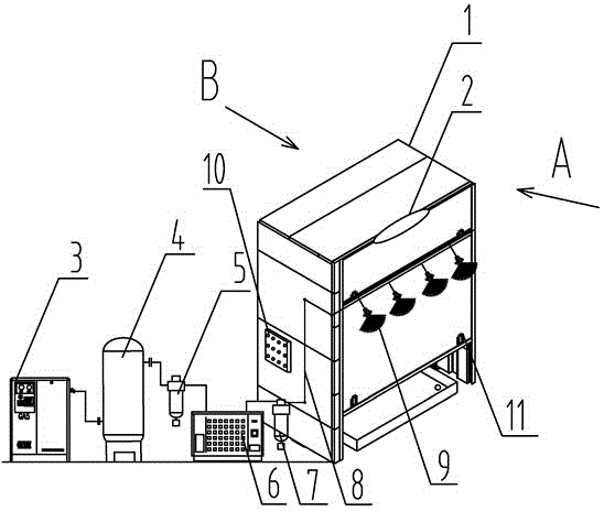
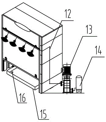
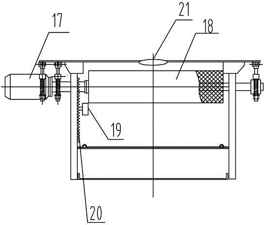
[0012] Referring to the accompanying drawings, a prefabricated component cleaning fuel injection machine includes a door frame 1, a tray inlet sensor 2, an air compressor 3, an air storage tank 4, a primary filter 5, a cold dryer 6, a medium filter 7, Compressed air pipeline 8, two-phase flow spray assembly 9, operation table 10, tray support wheel 11, oil pipeline 12, oil pump 13, oil storage tank 14, oil leakage residue tray 15, oil outlet hole 16, cleaning device motor 17. Steel cylinder cleaner 18, side mold cleaner 19, lifting device 20, tray outlet sensor 21, facing the left side of the spray master 9, an air pressure system for supplying compressed air to the equipment is arranged, and the air pressure is respectively arranged in sequence Machine 3, air storage tank 4, primary filter 5, cold dryer 6 and intermediate filter 7 are connected by compressed air pipeline 8, and console 10 is arranged on the left side wall of door frame 1, facing The oil supply system for supp...


PUM


Abstract

The invention discloses a prefabricated part sweeping and oil spraying machine applied to the technical field of precast concrete parts. The machine comprises a portal, a tray inlet sensor, an air compressor, a gas storage tank, a refrigerated air dryer, a primary effect filter, a medium effect filter, an oil storage tank, an oil leakage residue disk, a sweeping device motor, a lifting device, a tray outlet sensor and the like. An air compression system used for providing compressed air for the machine is arranged opposite to the left side of a spray assembly, the air compressor, the gas storage tank, the primary effect filter, the refrigerated air dryer and the medium effect filter are arranged in sequence and are connected through compressed air pipelines, and an operation table is arranged on the left side wall of the portal. An oil supply system for providing oil for the machine is arranged opposite to the right side of the spray assembly, and an oil pump and the oil storage tank are arranged in sequence and connected through an oil pipe. The prefabricated part sweeping and oil spraying machine integrates a sweeping system and an oil spraying system, fan-shaped film oil spraying is even, two steel column sweepers can achieve non-dead-corner sweeping, the machine is very easy to operate, low in cost, convenient to install, stable in work, safe, reliable and easy and convenient to maintain, and working is easy.

Description

technical field [0001] The invention relates to a prefabricated component cleaning oil sprayer in the technical field of concrete prefabricated components. Background technique [0002] At present, the production of reinforced concrete components has entered a new era. Large-scale, automated, and intelligent production lines have replaced old-fashioned production methods. Based on the understanding of the production technology of the concrete prefabricated component equipment manufacturing industry at home and abroad, it is found that the oil spraying process before the concrete construction tray enters the kiln body and the cleaning tray process after leaving the kiln require two types of equipment that occupy a large area to operate, and It consumes a lot of time, manpower and material resources, and is often accompanied by problems such as uneven oil film spraying and unclean pallet cleaning. However, all production equipment manufacturers have not effectively solved th...

Claims


Application Information

Patent Timeline
IPC IPC(8): B28B11/24B05B15/12B05B13/00B05B1/04B08B1/02
CPCB05B1/04B05B7/0416B05B13/0278B28B11/245B28B17/00B08B1/12B08B1/32
Inventor 张琼哲张伟谢庆军黄鑫董继卿孙斌李勇冯松涛
Owner NORTHERN HEAVY IND GRP CO LTD
Learn More