
Oil spray machine rotary joint

A technology of rotary joint and fuel injection machine, which is applied in the field of mechanical devices, can solve the problems of non-rotating function and uneven fuel injection, and achieve the effect of uniform fuel injection

Inactive Publication Date: 2019-06-14
NANTONG HENGDA MACHINERY MFG
View PDF4 Cites 0 Cited by
  • Summary
  • Abstract
  • Description
  • Claims
  • Application Information

AI Technical Summary

Problems solved by technology

However, the existing fuel injection nozzles do not have the function of rotation during the fuel injection process, resulting in uneven fuel injection, so it is necessary to provide a technical solution to solve such technical problems

Method used


Image

  • Oil spray machine rotary joint

Examples


Embodiment Construction

[0010] The present invention will be further described below in conjunction with the accompanying drawings and specific embodiments.

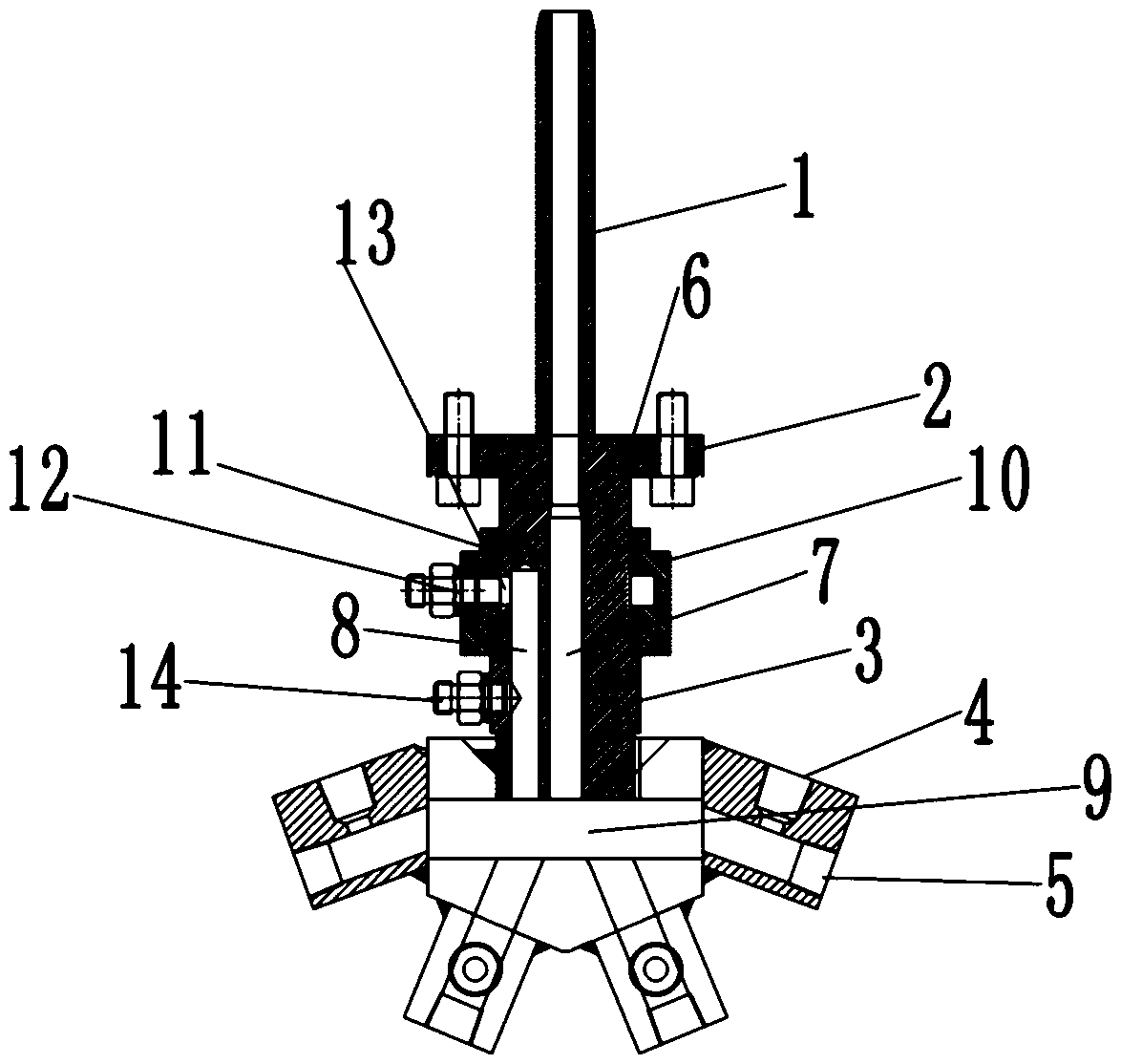
[0011] figure 1 Middle: air duct 1, flange plate 2, oil-gas mixing part 3, oil pipe interface 4, nozzle interface 5, bearing 6, high-pressure air chamber 7, oil chamber 8, oil-gas mixing chamber 9, oil pipe joint sleeve 10, annular oil seal 11 , oil pipe interface 12, oil inlet hole 13, transition interface 14.

[0012] A rotary joint of a fuel injection machine. The rotary joint of a fuel injection machine includes an air conduit 1, a flange 2, an oil-gas mixing piece 3, and a joint assembly. The joint assembly contains an oil pipe interface 4 and communicates with the oil pipe interface 4. The nozzle interface 5, the flange 2 is movably connected with the oil-gas mixing part 3 through the bearing 6, and the gas transmission conduit 1 and the oil-gas mixing part 3 can be driven to rotate by the motor.

[0013] The oil-gas mixing part 3 is pr...


PUM


Abstract

The invention discloses an oil spray machine rotary joint which comprises a gas transmission guide pipe1, a flange plate 2, an oil-gas mixing part 3 and a joint assembly. The joint assembly comprisesan oil pipe connector 4 and a nozzle connector 5, the flange plate 2 is movably connected with the oil-gas mixing part 3 through a bearing 6, the oil-gas mixing part 3 is internally provided with a high pressure gas cavity 7, an oil cavity 8 and an oil-gas mixing cavity 9, and a pipe cavity of the gas transmission guide pipe 1 communicates with the high pressure gas cavity 7. The oil spray machinerotary joint has the beneficial effects that rotation and oil spraying can be carried out at the same time, oil and gas are supplied respectively, and therefore oil spraying is more uniform.

Description

technical field [0001] The invention relates to a mechanical device, in particular to a rotary joint of a fuel injector. Background technique [0002] During the brick making process, a layer of oil is applied to the mold to help release the mold. Due to the effect of the oil layer, the billet and the mold will not be bonded. It has a good prominent effect. However, the existing fuel injection nozzle does not have the function of rotation during the fuel injection process, thereby causing uneven fuel injection. Therefore, it is necessary to provide a technical solution to solve such technical problems. Contents of the invention [0003] The present invention provides a rotary joint for a fuel injector based on the deficiency of the background technology. The purpose of designing and developing this device is that the device can realize fuel spraying while rotating, so that the fuel spraying is more uniform. [0004] The present invention provides the following technical...

Claims


Application Information

Patent Timeline
Patent Type & Authority Applications(China)
IPC IPC(8): B28B11/04
Inventor 崔恒全杨世玉于银龙
Owner NANTONG HENGDA MACHINERY MFG
Learn More