Welding method of air cooled condenser single row tube and tube plate employing carbon dioxide and argon mixed gas protection

An air-cooled condenser and carbon dioxide technology, which is applied in welding equipment, welding accessories, arc welding equipment, etc., can solve the problems of welding quality not meeting the requirements, welding process not meeting the requirements, welding seam strength and debris, etc. , to avoid solder bumps, small metal spatter, and improve mechanical properties

Active Publication Date: 2015-04-01
LONGHUA TECHNOLOGY GROUP (LUOYANG) CO LTD
View PDF5 Cites 4 Cited by
  • Summary
  • Abstract
  • Description
  • Claims
  • Application Information

AI Technical Summary

Problems solved by technology

[0002] At present, as the promotion of air-cooled condensers in my country becomes more and more common, the use of air-cooled condensers has also entered various fields, and the country's requirements for the strength and hardness of air-cooled condensers also tend to be higher. With the improvement of the steel type grade, under the welding conditions of sudden heat and sudden cooling, it is easy to produce hardened martensitic structure, which leads to the generation of welding cold cracks and the embrittlement of the welding heat-affected zone. In order to ensure the safe use of the structure, now Artificial argon arc welding is usually used, the welding speed is slow, the efficiency is low, and defects such as pores often occur in welding
Because the country has relatively high welding requirements for air-cooled condensers, if the method is improper or the welding process does not meet the requirements, the quality of the welding will not meet the requirements, such as the strength of the weld seam, the debris in the weld seam, etc.

Method used


Image

  • Welding method of air cooled condenser single row tube and tube plate employing carbon dioxide and argon mixed gas protection
  • Welding method of air cooled condenser single row tube and tube plate employing carbon dioxide and argon mixed gas protection
  • Welding method of air cooled condenser single row tube and tube plate employing carbon dioxide and argon mixed gas protection

Examples


Embodiment 1

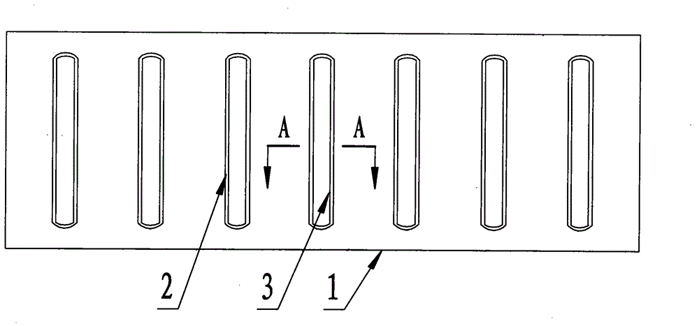
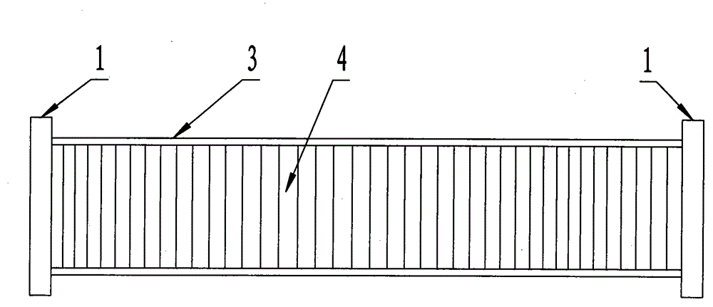
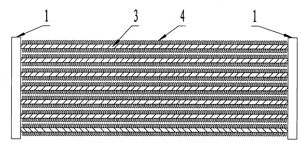
[0039] In the first step, the single-row tube 3 is installed on the tube plate 1, and at least five single-row tube mounting holes 2 are arranged side by side on the tube plate 1, and the distance between two adjacent single-row tube mounting holes 2 is equal, and the single-row tube The end faces of the two ends of the tube 3 are polished to be smooth, clean and free of dust. Remove the rust on the inner wall of the single-row tube installation hole 2 on the tube plate 1 to be welded. The two ends are inserted into the single-row tube installation holes 2 of the two tube plates 1, and the two sides of the single-row tube 3 are provided with cooling fins 4, and the end faces of the single-row tube 3 are arranged in the single-row tube installation holes 2, and the single-row tube 3 The distance between the end face of the row pipe 3 and the end face of the tube plate 1 is H, the end face of the single row pipe 3 and the inner wall of the single row pipe installation hole 2 form...

Embodiment 2

[0053] In the first step, the single-row tube 3 is installed on the tube plate 1, and at least five single-row tube mounting holes 2 are arranged side by side on the tube plate 1, and the distance between two adjacent single-row tube mounting holes 2 is equal, and the single-row tube The end faces of the two ends of the tube 3 are polished to be smooth, clean and free of dust. Remove the rust on the inner wall of the single-row tube installation hole 2 on the tube plate 1 to be welded. The two ends are inserted into the single-row tube installation holes 2 of the two tube plates 1, and the two sides of the single-row tube 3 are provided with cooling fins 4, and the end faces of the single-row tube 3 are arranged in the single-row tube installation holes 2, and the single-row tube 3 The distance between the end face of the row pipe 3 and the end face of the tube plate 1 is H, the end face of the single row pipe 3 and the inner wall of the single row pipe installation hole 2 form...

Embodiment 3

[0067] In the first step, the single-row tube 3 is installed on the tube plate 1, and at least five single-row tube mounting holes 2 are arranged side by side on the tube plate 1, and the distance between two adjacent single-row tube mounting holes 2 is equal, and the single-row tube The end faces of the two ends of the tube 3 are polished to be smooth, clean and free of dust. Remove the rust on the inner wall of the single-row tube installation hole 2 on the tube plate 1 to be welded. The two ends are inserted into the single-row tube installation holes 2 of the two tube plates 1, and the two sides of the single-row tube 3 are provided with cooling fins 4, and the end faces of the single-row tube 3 are arranged in the single-row tube installation holes 2, and the single-row tube 3 The distance between the end face of the row pipe 3 and the end face of the tube plate 1 is H, the end face of the single row pipe 3 and the inner wall of the single row pipe installation hole 2 form...


PUM

PropertyMeasurementUnit
diameteraaaaaaaaaa

Abstract

Provided is a welding method of air cooled condenser single row tube and tube plate employing carbon dioxide and argon mixed gas protection; in the welding process, argon and carbon dioxide gas mixed by volume percent is used, no defect is existed, the hot compress rate of the welded joint is the best, the quality of the welding joint is stable, and splatter is not existed; the single row tube is prevented from being damaged by external force, solder collision is avoided, and the sealing quality is ensured; the existing welding method using only the carbon dioxide as the protective gas is changed, the welding method employing carbon dioxide and argon mixed gas protection is used, thereby meeting the requirements that the electric arc is stable, the metal splatter is less, the formed welding joint is good in appearance, the impact toughness of the welding joint is good, and the welding technology is good in effect, and the like.

Description

technical field [0001] The invention relates to the technical field of dissimilar metal welding, in particular to a welding method for protecting a single-row tube and a tube plate of an air-cooled condenser with a mixed gas of carbon dioxide and argon. Background technique [0002] At present, as the promotion of air-cooled condensers in my country becomes more and more common, the use of air-cooled condensers has also entered various fields, and the country's requirements for the strength and hardness of air-cooled condensers also tend to be higher. With the improvement of the steel type grade, under the welding conditions of sudden heat and sudden cooling, it is easy to produce hardened martensitic structure, which leads to the generation of welding cold cracks and the embrittlement of the welding heat-affected zone. In order to ensure the safe use of the structure, now Artificial argon arc welding is usually used, the welding speed is slow, the efficiency is low, and defec...

Claims


Application Information

Patent Timeline
Patent Type & Authority Applications(China)
IPC IPC(8): B23K9/16B23K9/32
CPCB23K9/16B23K9/32
Inventor 陈斌郭昆张润龙张丹丹董菊新
Owner LONGHUA TECHNOLOGY GROUP (LUOYANG) CO LTD
Why Eureka
Try Eureka