Flat film layer spray orifice structure and ink-jet printer

A thin film layer and nozzle hole technology, applied in the field of inkjet printers, can solve problems such as clogging, alignment error, nozzle hole pollution, etc., and achieve the effect of not easy to damage, easy to manufacture, and strong damage

Inactive Publication Date: 2016-06-15
SUZHOU INST OF NANO TECH & NANO BIONICS CHINESE ACEDEMY OF SCI +1
View PDF17 Cites 0 Cited by
  • Summary
  • Abstract
  • Description
  • Claims
  • Application Information

AI Technical Summary

Problems solved by technology

[0004] 1. There is an alignment error when the polyimide film is pasted in alignment, and the nozzle hole deviates from the target position
[0005] 2. When the polyimide film is attached to the top of the wall, there will be deviations in the adhesion uniformity and adhesion of the polyimide film
[0007] 1. There will be grooves between

Method used


Image

  • Flat film layer spray orifice structure and ink-jet printer
  • Flat film layer spray orifice structure and ink-jet printer
  • Flat film layer spray orifice structure and ink-jet printer

Examples


Example Embodiment

[0022] The preferred embodiments of the present invention will be described in detail below with reference to the accompanying drawings, so that the advantages and features of the present invention can be more easily understood by those skilled in the art, so that the protection scope of the present invention can be more clearly defined.

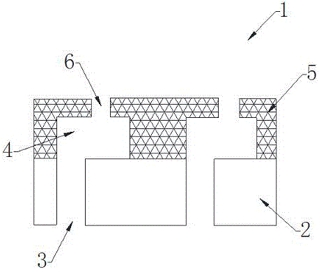
[0023] Such as image 3 As shown, a flat orifice film layer structure 1 includes a substrate 2. A plurality of ink inlet channels 3 are provided on the substrate 2, and the surface of the substrate 2 is flatly covered with a film layer 5. A number of pressure cavities 4 are arranged inside the film layer 5, and the pressure cavities 4 and the ink inlet channels 3 are in one-to-one correspondence and communicate with each other. The surface of the film layer 5 is also provided with a number of nozzle holes 6. The nozzle holes 6 Correspond to the pressure chamber 4 one by one and communicate with each other.

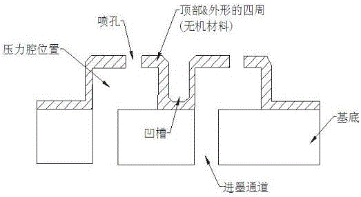
[0024] Such as Figure 4 As shown, a ...


PUM


Abstract

The invention discloses an orifice structure of a flat film layer and an inkjet printer using the orifice structure of a flat film layer. Cover a film layer evenly, and set several pressure chambers inside the film layer. The pressure chambers correspond to the ink inlet channels and communicate with each other. There are also several nozzle holes on the surface of the film layer, and the nozzle holes correspond to the pressure chambers one by one. And communicate with each other, there may also be interlayers between the pressure chambers, and the film layer is made of organic materials. Because the thin film layer of the flat orifice thin film layer structure of the present invention is formed of organic materials as a whole, it is easy to manufacture and does not form grooves on the surface, and does not cause accumulation of ink and other pollutants; the wall of the pressure chamber is firm and not easy to damage, and more Facilitate mass production.

Description

technical field [0001] The invention relates to an orifice structure of a flat film layer, more precisely, an orifice structure of a flat film layer used in inkjet printing technology, and an inkjet printer using the orifice structure of a flat film layer. Background technique [0002] At present, there are two traditional structures for implementing pressure chambers in the industry: [0003] Such as figure 1 The main feature of the existing structure shown is that the material of the top is different from that of the wall, and its realization process is relatively complicated, and it is difficult to mass-produce it by conventional MEMS methods. For this structure, the shape of the pressure chamber is first formed by photolithography, and then the polyimide film that has been laser-drilled to form nozzle holes is pasted on the top of the wall by alignment. The disadvantages of this structure are: [0004] 1. There is an alignment error when the polyimide film is pasted i...

Claims


Application Information

Patent Timeline
IPC IPC(8): B41J2/14B41J2/01B32B3/26
CPCB41J2/14B32B3/266B41J2/01
Inventor 李令英宋佳丽谢永林
Owner SUZHOU INST OF NANO TECH & NANO BIONICS CHINESE ACEDEMY OF SCI
Why Eureka
Try Eureka