
A photoacoustic imaging signal multiplexing device and method

A signal multiplexing and photoacoustic imaging technology, applied in the field of optical imaging, can solve the problems of reduced work stability, reduced laser energy, high cost of high-speed multi-channel data acquisition modules, etc., to save system costs, reduce laser energy, and reduce desired effect

Active Publication Date: 2016-11-30
SHANGHAI JIAO TONG UNIV
View PDF5 Cites 0 Cited by
  • Summary
  • Abstract
  • Description
  • Claims
  • Application Information

AI Technical Summary

Problems solved by technology

At present, the challenge of photoacoustic microscopy in clinical application is mainly the energy safety of laser irradiation, and the ultrasonic signal induced by low-energy laser irradiation on tissue under the safety threshold is very weak, so ultra-high sensitivity and high signal-to-noise are required Compared with the ultrasonic sensor, however, there are no products that meet the technical requirements in the market
[0004] After searching the existing technology, it was found that the foreign literature: "Laser-scanning photoacousticmicroscopy with ultrasonic phased array transducer, Biomed Opt Express.2012; 3(11):2694-9." proposed a multi-channel probe array to acquire ultrasonic signals , and then use the beamforming algorithm to fuse multi-channel information, which can effectively improve the imaging signal-to-noise ratio and reduce the system’s requirements for laser energy and probe performance. However, the high-speed multi-channel data acquisition module is expensive, and its working stability will also vary with the number of channels. increase and decrease
[0005] Chinese patent (application number: 201210043841.1; publication number: CN102621067) discloses a real-time photoacoustic imaging system based on two-dimensional laser galvanometer scanning. The system uses laser scanning method to collect photoacoustic signals in the form of unit probes or probe arrays. However, it does not involve the method of optimizing the imaging signal-to-noise ratio through the probe array to reduce the laser energy and meet the clinical application standards

Method used


Image

  • A photoacoustic imaging signal multiplexing device and method
  • A photoacoustic imaging signal multiplexing device and method

Examples


Embodiment Construction

[0032] The present invention will be described in detail below in conjunction with the accompanying drawings and specific embodiments. This embodiment is carried out on the premise of the technical solution of the present invention, and detailed implementation and specific operation process are given, but the protection scope of the present invention is not limited to the following embodiments.

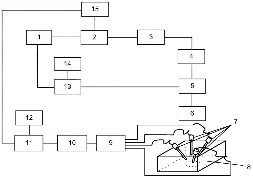
[0033] Such as figure 1 As shown, this embodiment provides a photoacoustic imaging signal multiplexing device, including an optical scanning part and a signal acquisition part, wherein the optical scanning part includes a scanning control computer 14, a vibrating mirror control board 13, a laser generating module and a vibrating mirror module, the scanning control computer 14 is respectively connected to the laser generation module and the vibration mirror module through the vibrating mirror control board 13; connect.

[0034] The laser generating module includes a laser light sourc...


PUM


Abstract

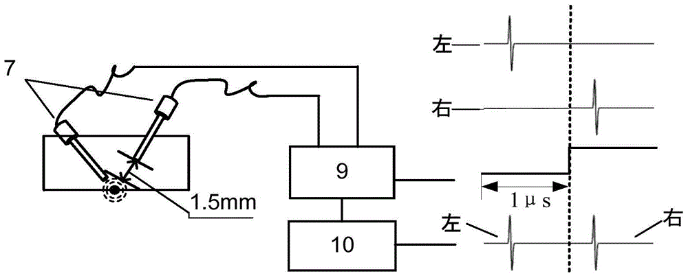
The invention relates to a device and a method for multiplexing photoacoustic imaging signals. The device comprises an optical scanning part and a signal acquisition part, wherein the optical scanning part comprises a scanning control computer, a galvanometer control board card, a laser generation module and a galvanometer module, and the scanning control computer is respectively connected with the laser generation module and the galvanometer module through the galvanometer control board card; the signal acquisition part comprises an ultrasonic probe group, a signal selection module and a data acquisition module which are connected in sequence, and the data acquisition module is connected with the laser generating module; the laser generating module is controlled for sending out laser, the deflection angle of the galvanometer module is controlled, the laser is focused on a sample through the galvanometer module to send out an ultrasonic signal, and meanwhile the data acquisition module is triggered; the ultrasonic signal is obtained by the ultrasonic probe group, and is transmitted to the data acquisition module after multiplexing of a single-channel multi-probe signal is realized through the signal selection module. Compared with the prior art, the device has the advantages of improving the imaging SNR (Signal to Noise Ratio), reducing laser energy and probe performance requirement and the like.

Description

technical field [0001] The invention relates to the field of optical imaging, in particular to a photoacoustic imaging signal multiplexing device and method. Background technique [0002] The basic principle of photoacoustic imaging technology is that when pulsed laser light is irradiated into biological tissue, ultrasonic signals will be generated due to the light absorption and thermal expansion of the tissue. This photoinduced ultrasonic signal carries the light absorption characteristic information of the tissue. By measuring these ultrasonic signals can An image of the light absorption distribution in the tissue is reconstructed. Therefore, photoacoustic imaging has the dual advantages of high optical contrast and deep acoustic penetration, and has broad application prospects in the fields of life science research and clinical medical diagnosis. [0003] The laser scanning optical resolution photoacoustic microscopic imaging system is based on galvanometer scanning to ...

Claims


Application Information

Patent Timeline
Patent Type & Authority Patents(China)
IPC IPC(8): A61B5/00A61B8/00
CPCA61B5/0095
Inventor 柴新禹周传清李林
Owner SHANGHAI JIAO TONG UNIV
Learn More