
Uplink and downlink unified resource allocation method

An associated and step-by-step technology, applied in electrical components, wireless communications, etc., can solve problems such as throughput reduction, resource conflict, and waste of PUCCH resources, and achieve the effect of improving uplink throughput and reducing the number of occupied resources.

Inactive Publication Date: 2015-03-25
POTEVIO INFORMATION TECH
View PDF5 Cites 7 Cited by
  • Summary
  • Abstract
  • Description
  • Claims
  • Application Information

AI Technical Summary

Problems solved by technology

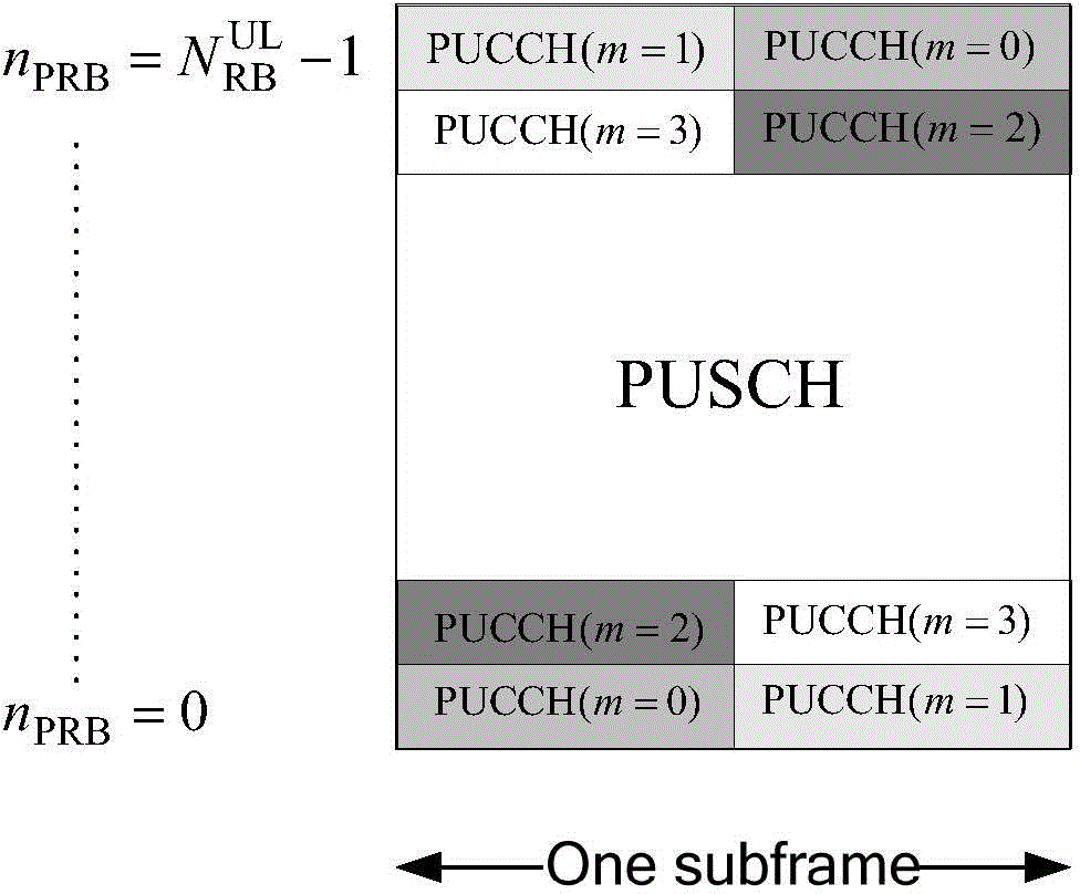
[0011] In solution 1, the number of PUCCH resources is determined by the pre-configured CQI / RI / PMI and SR period, and the maximum CCE index corresponding to the number of PDCCH symbols in the downlink transmission subframe, it is difficult to make full use of the characteristics of PUCCH periodic resources, and The feature of PUSCH carrying ACK / NACK feedback along the road will cause the reporting of ACK / NACK detection results of downlink service transmission to occupy more PUCCH resources, reducing the number of available resources for PUSCH, resulting in a decrease in uplink throughput;
[0012] In the second solution, a certain amount of resources is reserved in a semi-static manner, and adjusted according to the usage efficiency after a period of time, which cannot flexibly adapt to changes in user and service requirements in the system. If a large number of resources are reserved, PUCCH resources will be wasted , less reservation will cause the ACK / NACK reporting position of some users to conflict with the PUSCH resource, or the problem that some users cannot be scheduled

Method used


Image

  • Uplink and downlink unified resource allocation method
  • Uplink and downlink unified resource allocation method

Examples


Embodiment Construction

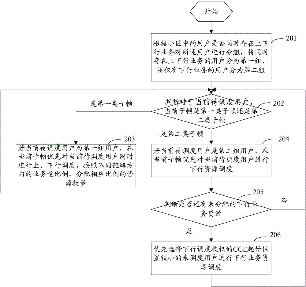
[0027] Different from the existing technical solutions that independently allocate resources between the uplink and downlink traffic channels, and between the uplink and downlink control channels and traffic channels, or semi-statically reserve PUCCH resources, the uplink and downlink Joint resource allocation methods include:

[0028] A. Divide users who have both uplink and downlink services in the cell into the first group, and divide users who only have downlink services in the cell into the second group;

[0029] A. Divide users who have both uplink and downlink services in the cell into the first group, and divide users who only have downlink services in the cell into the second group;

[0030] B. Judging whether the current subframe is a first-type subframe or a second-type subframe for the current user to be scheduled, if it is a first-type subframe, perform step C, and if it is a second-type subframe, perform step D; the first type The subframe meets the following co...


PUM


Abstract

The invention discloses an uplink and downlink unified resource allocation method, including the steps of: preferentially performing uplink and downlink scheduling on users with uplink and downlink business at the same time at a first sub-frame, allocating resource quantities with corresponding proportions according to the business volume proportions in different link directions, and preferentially performing downlink resource scheduling on the users only with downlink business at a second sub-frame. The subsequently relevant uplink sub-frame of the first sub-frame is not report time of a CQI (Channel Quality Indicator) / PMI (Precoding Matrix Indicator) or SRI (Scheduling Request Indicator) of the user; the subsequently relevant uplink sub-frame of the second sub-frame is the report time of the CQI / PMI or SRI of the user; and in the subsequently relevant uplink sub-frame, report time of an ACK / NACK (Acknowledgement / Negative-Acknowledgement) transmitted by the downlink business is also the target uplink sub-frame authorized by the uplink scheduling in the scheduling sub-frame at the same time. According to the uplink and down link unified resource allocation method, promotion of uplink handling capacity can be achieved by increasing the available resource quantity of a PUSCH (Physical Uplink Control Channel).

Description

technical field [0001] The present application relates to the technical field of mobile communication, and in particular to a method for allocating uplink and downlink joint resources. Background technique [0002] In a wireless communication system, for accurate and efficient communication between a base station and a user equipment (UE), the UE needs to feed back uplink control information (Uplink Control Information, UCI) to the base station. Uplink control information includes: Scheduling Request Indicator (SR); Acknowledgment / Negative-Acknowledgment (ACK / NACK); Channel Quality Indicator (CQI), Rank Indicator (Rank Indicator, RI ) and Precoding Matrix Indicator (PrecodingMatrix Indicator, PMI). Among them, SR is used for the UE to request uplink resources from the base station, ACK / NACK is used for the UE to indicate to the base station whether the downlink data is received correctly, and information such as CQI is used for the UE to indicate the measured downlink chann...

Claims


Application Information

Patent Timeline
Patent Type & Authority Applications(China)
IPC IPC(8): H04W72/04H04W72/12
CPCH04W72/21H04W72/23
Inventor 韦玮吕征南陶雄强
Owner POTEVIO INFORMATION TECH
Learn More