A Neighbor Node Discovery Method Based on Beamforming Antenna

A technology of neighbor node discovery and beamforming, applied in wireless communication, access restriction, network data management, etc., can solve problems such as high geographical environment requirements and unfavorable network security, so as to reduce hardware overhead, improve time efficiency, reduce effect of difficulty

Active Publication Date: 2019-03-29
SHANGHAI JIAO TONG UNIV
View PDF1 Cites 0 Cited by
  • Summary
  • Abstract
  • Description
  • Claims
  • Application Information

AI Technical Summary

Problems solved by technology

[0005] At the same time, some existing neighbor node methods are mainly based on synchronization, require additional hardware such as GPS, have high requirements on the geographical environment, and are not conducive to network security.

Method used


Image

  • A Neighbor Node Discovery Method Based on Beamforming Antenna
  • A Neighbor Node Discovery Method Based on Beamforming Antenna
  • A Neighbor Node Discovery Method Based on Beamforming Antenna

Examples


Embodiment 1

[0038] The communication method of the present invention specifically includes the following steps:

[0039] The first step is to import the network range and the total number of nodes in this range into the node.

[0040] In the second step, all nodes enter the omni-discovery phase. According to the data in the first step, the node density is calculated, and then the average number of neighbor nodes for each node is calculated. The interval at which the node sends the training sequence obeys the exponential distribution with the parameter λ, and the node sends the training sequence at the time outside the receiving mode. Calculate the optimal λ of the system according to the average number of neighbor nodes. The optimal λ can be expressed as:

[0041]

[0042] Where k represents the average number of neighbor nodes, and τ represents the duration of the training sequence sent.

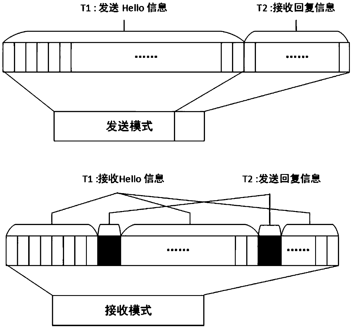
[0043] In the third step, in the omnidirectional discovery phase, when the node in the receiving mode rec...

Embodiment 2

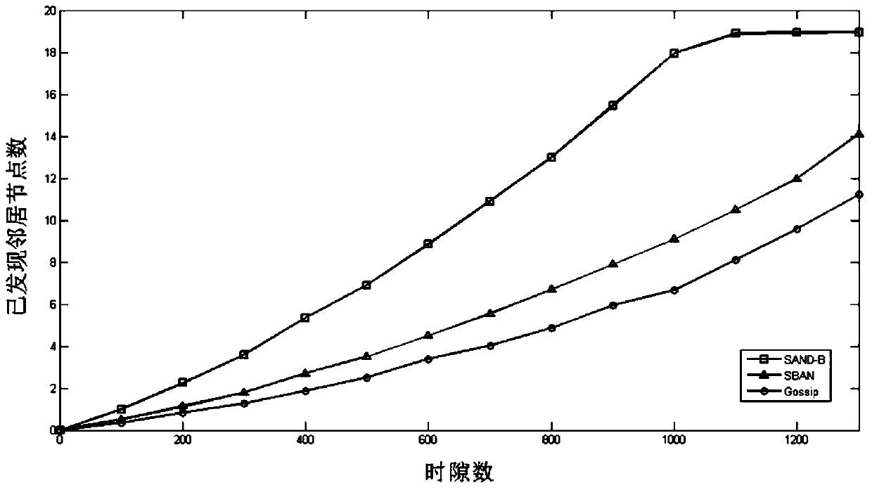
[0054] In the first step, the area is 3.14×10 8 m 2 In the circular area of, deploy 2000 nodes, import the area area and the total number of nodes into the node, and the sending distance of the node is 1000m.

[0055] In the second step, according to the first step, the average number of neighbor nodes of the node is 19. Make the node send the training sequence interval to obey the parameter λ op Exponential distribution, where Other time in receiving mode

[0056] In the third step, the node updates and maintains the neighbor node direction information table, and enters the first discovered direction. If the direction of the training sequence has been recorded before, it will not be repeated.

[0057] The fourth step is to set the threshold of the neighbor node discovery ratio to 0.998 according to actual needs. The stay time of all nodes in the omnidirectional discovery phase is:

[0058] t a = -38e log0.002τ

[0059] After the omni-directional discovery is over, all nodes enter ...


PUM


Abstract

The invention relates to a neighbor node finding method based on a beam forming antenna. The method comprises the following steps that (1) a network range and the total number of nodes within the range are input; (2) the optimum distribution of intervals formed when an omnibearing finding stage sends Training sequences is calculated; (3) a receiving node maintains a neighbor node direction information table according to the Training sequences; (4) when the neighbor node direction finding proportion exceeds a threshold value, an orientation finding stage is started; (5) an independent transmitting and receiving mode is selected before a period starts; (6) the node runs a slow-scanning Hello information mechanism; (7) the node receiving Hello information maintains a neighbor node to-be-relied information table, a rapid reply mechanism is made to run, the node in the receiving mode is selected to enter a rely information receiving stage. Compared with the prior art, on the basis of the asynchronous time slot, the reliability of the neighbor nodes is ensured through two handshakes, and the neighbor nodes can be rapidly and effectively found.

Description

Technical field [0001] The present invention relates to the technical field of wireless communication, in particular to a neighbor node discovery method based on beamforming antennas. Background technique [0002] Wireless multi-hop self-organizing network (MANET) can realize mutual communication between nodes without using the existing network infrastructure, and has a wide range of applications in military communications, sensor networks, and disaster relief. The wireless multi-hop self-organizing network that adopts the traditional omnidirectional antenna design has the problems of more conflicts and lower throughput. With the development of antenna technology, beamforming technology brings advantages in terms of transmission distance, anti-interference performance, space division multiplexing, and network performance. However, making full use of these advantages of beamforming antennas requires fast and accurate neighbor node discovery methods. [0003] The neighbor node disc...

Claims


Application Information

Patent Timeline
Patent Type & Authority Patents(China)
IPC IPC(8): H04W8/00H04W48/16
CPCH04W8/00H04W40/24H04W48/16
Inventor 孙大佳李悦丁良辉杨峰钱良
Owner SHANGHAI JIAO TONG UNIV
Why Eureka
Try Eureka