
SLNR-based beam forming method for CoMP-JP system

A beamforming method and forming technology, applied in the field of precoding algorithms, can solve problems such as unbalanced bit error performance among substreams

Active Publication Date: 2015-03-25
HARBIN INST OF TECH
View PDF3 Cites 2 Cited by
  • Summary
  • Abstract
  • Description
  • Claims
  • Application Information

AI Technical Summary

Problems solved by technology

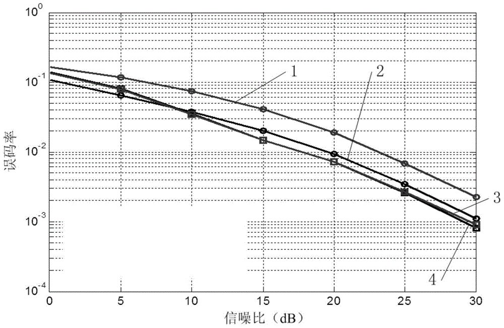
[0021] The present invention is to solve the problem of unbalanced bit error performance between sub-streams when SLNR is transmitting in multiple streams. The present invention provides a beamforming method based on SLNR in a CoMP-JP system

Method used


Image

  • SLNR-based beam forming method for CoMP-JP system
  • SLNR-based beam forming method for CoMP-JP system
  • SLNR-based beam forming method for CoMP-JP system

Examples


specific Embodiment approach 1

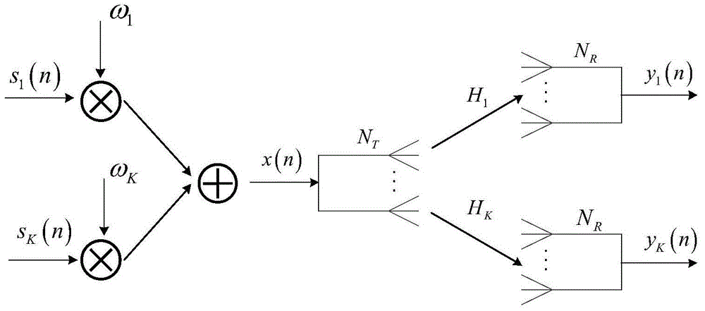
[0087] Specific implementation mode one: see Figure 7 Describe this embodiment, the SLNR-based beamforming method in the CoMP-JP system described in this embodiment, the method includes the following steps:

[0088] Step 1: Obtain the original precoding vector and the original precoding matrix by using the existing SLNR precoding algorithm for each user;

[0089] Step 2: Calculate the weighting coefficient for each user based on the original precoding vector obtained in step 1 and based on the two criteria of eliminating inter-stream difference and inter-stream interference, and then construct a linear transformation representation matrix;

[0090] Step 3: Using the original precoding vector as a base, use the obtained representation matrix for constructing linear transformation to perform linear transformation on the original precoding matrix, construct a set of new precoding vectors, and then obtain the WSLNR precoding matrix;

[0091] Step 4: Use the obtained WSLNR precod...

specific Embodiment approach 2

[0092] Embodiment 2: The difference between this embodiment and the SLNR-based beamforming method in the CoMP-JP system described in Embodiment 1 is that the original precoding matrix in step 1 is

[0093] arg max ω k ∈ C N T × u Tr ( ω k H H k H H k ω k ) Tr [ ω k H ...

specific Embodiment approach 3

[0102] Embodiment 3: The difference between this embodiment and the SLNR-based beamforming method in the CoMP-JP system described in Embodiment 2 is that for a dual-stream transmission system, T k The first two columns of are used as the original precoding matrix For user k, the precoding vectors corresponding to the two parallel data streams are respectively set to ω k,1 and ω k,2 ,Right now

[0103] ω k opt = β k T k I 2 0 = [ ω k , 1 , ω k , 2 ] ,

[0104] Among them, for user ...


PUM


Abstract

The invention discloses an SLNR-based beam forming method for a CoMP-JP system and belongs to the field of beam forming for a mobile communication system. By the adoption of the SLNR-based beam forming method for the CoMP-JP system, the problem that when the SLNR algorithm is used for transmission of multiple streams, the bit error rate performances of substreams are not balanced is solved. The SLNR-based beam forming method for the CoMP-JP system comprises the steps that firstly, an original precoding vector and an original precoding matrix are obtained for each user according to the existing SLNR precoding algorithm; secondly, for each user, the weighting coefficient is obtained according to the corresponding precoding vector obtained in the first step based on the two criteria of eliminating the difference between the streams and eliminating interference between the streams, and then an expression matrix used for linear transformation is constructed; thirdly, with the original precoding vectors as the bases, linear transformation is conducted on the original precoding matrix by means of the constructed expression matrix used for linear transformation, so that a group of new precoding vectors are obtained, and then a WSLNR precoding matrix is obtained; fourthly, signal forming is conducted by means of the obtained WSLNR precoding matrix, and then forming of the original precoding vectors is completed. The SLNR-based beam forming method is mainly used for beam forming in the communication field.

Description

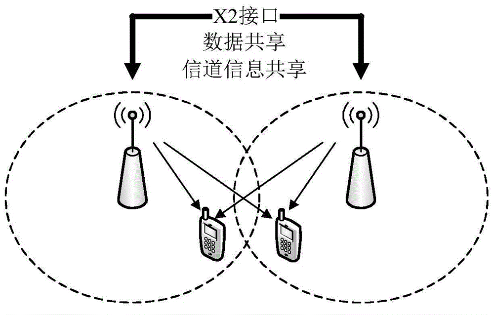
technical field [0001] The invention belongs to the field of beam forming in a mobile communication system, and in particular relates to a precoding algorithm based on linear transformation and applied to a multi-cell multi-stream joint processing system. Background technique [0002] CoMP is an effective inter-cell interference coordination technology in the LTE-A system. It utilizes multiple base stations to share information such as physical transmission resources, cooperate with each other for transmission or joint scheduling, optimize wireless data transmission, and realize multiple base stations participating in the same UE at the same time. Terminal communication. CoMP is the application of MIMO technology in multi-cell conditions, and implements intra-frequency networking and suppression or elimination of inter-cell interference through interference processing among multiple cells. The joint processing technology is a common scheme of downlink CoMP, which can conver...

Claims


Application Information

Patent Timeline
Patent Type & Authority Applications(China)
IPC IPC(8): H04B7/06
CPCH04B7/0413H04B7/0617
Inventor 吴玮田纯阳吴宣利刘宇琦沙学军李卓明刘井安
Owner HARBIN INST OF TECH
Learn More