MCU keyboard circuit capable of handling multiple keys pressed simultaneously and its implementation method

A technology of keyboard circuit and implementation method, applied in the input/output process of data processing, electrical digital data processing, input/output of user/computer interaction, etc., can solve the problem of excessive CPU time occupation, insufficient I/O resources, etc. problems, to achieve the effect of improving effectiveness, saving hardware resources and time, and saving MCU resources

Active Publication Date: 2017-06-20
LAUNCH TECH CO LTD
View PDF5 Cites 0 Cited by
  • Summary
  • Abstract
  • Description
  • Claims
  • Application Information

AI Technical Summary

Problems solved by technology

[0008] The object of the present invention is to provide a kind of MCU keyboard circuit and its implementation method that can handle multi-key pressing simultaneously, solve the problem of insufficient I / O resource of MCU system in the prior art;
[0009] Another object of the present invention is to provide a kind of MCU keyboard circuit and its implementation method that can handle multi-buttons pressed simultaneously, overcome the defect that takes up too much CPU time when processing and analyzing the multiple buttons that are pressed simultaneously in the prior art

Method used


Image

  • MCU keyboard circuit capable of handling multiple keys pressed simultaneously and its implementation method
  • MCU keyboard circuit capable of handling multiple keys pressed simultaneously and its implementation method
  • MCU keyboard circuit capable of handling multiple keys pressed simultaneously and its implementation method

Examples


Embodiment Construction

[0034] In order to make the object, technical solution and advantages of the present invention clearer, the present invention will be further described in detail below in conjunction with the accompanying drawings and embodiments. It should be understood that the specific embodiments described here are only used to explain the present invention, not to limit the present invention.

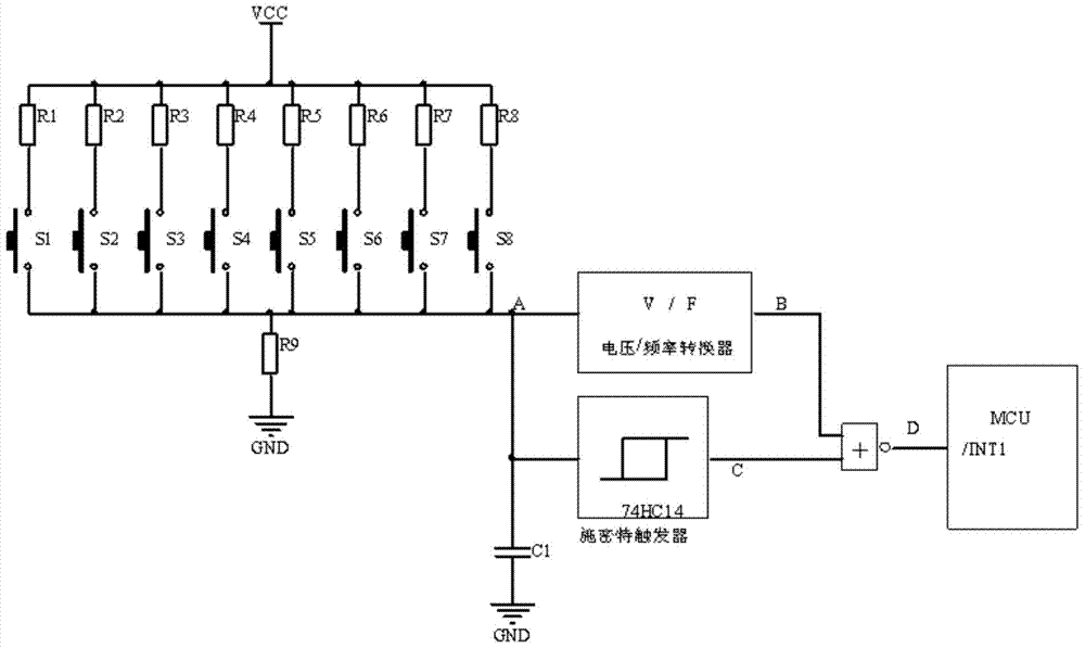
[0035] see figure 1 , the MCU keyboard circuit proposed by the present invention includes: M buttons S1, S2, ..., SM, and M resistors R1, R2, ..., RM corresponding to the buttons one by one, public resistance, capacitance, voltage / Frequency converter (V / F), Schmitt trigger, NOR gate, MCU. In this embodiment, the value of M is 8, that is, 8 keys and 8 resistors R are included.

[0036] Among them, one end of Ri is connected to the VCC power supply, and the other end is connected to one end of the button Si (1≤i≤M), and the other ends of all the buttons S are grounded through the common resistor R...


PUM


Abstract

The invention provides an MCU keyboard circuit capable of enabling multiple keys to be pressed simultaneously and an implementation method thereof. The keyboard circuit comprises an MCU, M keys from S1 to SM, M resistors from R1 to RM, a common resistor, a voltage / frequency converter, a Schmitt trigger and a NOR gate. One end of the Ri is connected to a VCC power source, the other end of the Ri is connected to one end of the key Si (1<=i<=M), and the other ends of all the keys are connected to a point A and are connected with the ground through the common resistor. The point A is connected with the input end of the voltage / frequency converter and the input end of the Schmitt trigger. The output end of the voltage / frequency converter is connected to one input end of the NOR gate, and the output end of the Schmitt trigger is connected to the other input end of the NOR gate, or the output end of the NOR gate is connected to a pin INT1 of the MCU. By means of the MCU keyboard circuit, hardware resources of the MCU are greatly saved, the processing time for pressing the multiple keys simultaneously is greatly shortened, and therefore the MCU keyboard circuit has the advantages of being simple, effective, reliable and the like.

Description

technical field [0001] The invention relates to the technical field of keyboards, in particular to an MCU keyboard circuit which is simple, efficient and particularly saves MCU hardware resources and can handle simultaneous pressing of multiple keys and an implementation method thereof. Background technique [0002] Usually, the implementation method of the keyboard circuit of the MCU is as follows: [0003] (1) Independent keyboard method [0004] Generally, when the number of keys is not greater than 8, this method can be used, and each key is connected to an I / O line of an MCU. In this way, several keys need to occupy several I / O lines of the MCU. This method takes up more hardware resources of the MCU. When multiple keys are pressed at the same time, it is necessary to use software to process multiple key values, which will take up more CPU time. [0005] (2) Matrix keyboard method [0006] Generally, when the number of keys is greater than 8, this method is often use...

Claims


Application Information

Patent Timeline
Patent Type & Authority Patents(China)
IPC IPC(8): G06F3/02
CPCG06F3/0202
Inventor 刘均邓芳鸿李剑锋
Owner LAUNCH TECH CO LTD
Why Eureka
Try Eureka